
Leaderboard


Popular Content
Showing content with the highest reputation since 04/20/2015 in all areas
-

Version 1.0.0
455 downloads
Here is my full size Velociraptor skeleton. Juste made for the challenge. Lenght: ~180cm Sculpted with Zbrush. Total printing time: ~392h. Printer: Ultimaker2+ Filament: PLA Speed: 30mm/s - 50mm/s Nozzle: 0,4mm Layers: 0,15mm Painting : acrylic paint (spray and brushe)22 points -
I'm Steve Cox, a member of the Utimaker Community. I'm an experienced engineer having spent many years in the automotive industry but I'm now focussed on the world of 3D technologies, specifically 3D product design and 3DPprinting. I'm an Autodesk Certified Instructor for Fusion 360, so many of the images in this post are taken from that design software but this post is not specific to that software but is about designing for 3D Printing and Additive Manufacturing. This is a first of a series of blog posts in this area that will be focussing on how engineering is interacting with the latest 3D technologies. Additive Manufacturing (AM) and 3D Printing (3DP) - whilst the way they produce an object from nowhere can often seem like modern-day magic, the truth is that in many ways they are no different to any other way of making things. Every method that we use to manufacture things has it’s own rules that we need to consider when designing. These rules are known as DFM – Design For Manufacture. This approach takes into account the pros and cons of the chosen manufacturing method to produce a design that can be made repeatably, reliably and to meet the intended function and life expectancy of the product. This way of thinking when applied to AM (or 3DP) is now becoming known as DfAM, or Design for Additive Manufacture. In reality there are two aspects of DfAM, the first we will deal with in this post where we will concentrate on the use of DfAM applied to detail features of the design to ensure manufacturability. The second aspect is using DfAM at the conceptual design to realise some of the unique capabilities that AM has to offer, and that will be covered in a later article. The rules of DfAM tend to be slightly different for each type of AM/3DP technology. Here we will be assuming that we are using Fused Deposition Modelling (FDM) 3DP but, for instance, in metal AM residual stresses build up in the part during manufacturing due to the high local energies applied by the laser or electron beam. These have to be taken into consideration if warping and possible early-life failure are to be avoided. So, in metal AM, the use of DfAM can involve designing out thick sections where heat build-up can be greatest. This is seldom a significant issue in FDM 3D printing. Two of the main DfAM considerations in FDM 3D printing are layer orientation and overhangs which we will take a closer look at here. Layer orientation When a detail design is being prepared for manufacture one of the first things to consider is the loads that will be applied to it, and 3D printing is no different. There can be potential weaknesses in 3D prints in the “welded” joints that exist between every layer which provide multiple potential crack propagation opportunities. So at the detail design stage the loading direction may need to be taken into account, which can in turn lead to a decision being made on the print direction to be used very early on and that will then set the tone for the rest of the design. In this particular case the stress analysis in Fusion 360 on a loaded side wall of a design shows that the peak stress occurs on the inside face of that wall near to it’s base which, if we were to print it in this orientation, will coincide with the end of a layer and hence one of these potential crack propagation sites : Which can lead to this : The better way of 3D printing this design to withstand this loading condition would be to orientate the printing direction by 90 degrees to ensure that the load is being applied along the layer lines rather than across them. The strength of a part with this layer orientation will be many times greater under the loading condition described previously, though the amount is difficult to objectively state since simulation software taking into account the layer construction of AM is still an emerging area of activity. So this is a DfAM consideration to think about at the very start of your design - what are the main load bearing directions and is it possible to optimise the design to ensure that the way that you will make the part which does not result in loads being applied across a layer? This is the single most effective step that you can take, but it may not always be possible to do that, in which case you need to employ mitigation factors into your design. The usual best practice in any design is, where possible, to add a fillet (or radius) at the base of the wall to counteract these high stresses. This reduces the local stress moves the higher stress point further up the side wall and is an optimal way of adding strength with the addition of minimal material. However, in AM/3DP it is often a better option to use an angled face rather than a curved face to achieve the same effect The reason for this different approach is that the "staircase" of layers in more uniform in the case of the angled face, whilst with a fillet radius the smooth blend into the base results in a longer first layer step which reduces it's effectiveness. So this is another aspect of DfAM where strategies used for other methods of manufacture may need to be subtly modified to make them most effective when using this particular method Overhangs Once the print direction has been selected then the design of overhangs, and preferably the elimination of as many of these as possible, can be addressed. Fewer overhangs means less requirement for support which leads to a more efficient print time, lower material usage and reduced post processing time for removal of supports This is the most obvious way to eliminate an overhanging feature : Things like this are simplistic and often easy to spot, but you may find that your design is more complex than this and there is a tendency to design from experience with traditional manufacturing methods and put in features that aren’t good for AM almost without thinking. For instance in this example of a flanged coupling the features with blind tapped holes for the connection have been designed with a feature that would cause no problem for a moulding process but produce an overhanging area for 3D printing (highlighted in red when viewed in Cura) With some re-examination it was possible to re-imagine these features like this which result in no overhang and hence no support. Rather than fill this post with lots of examples of individual examples of this kind of comparison my recommendation when engaging with DfAM is to regularly check your design in the slicing software as your design develops, looking for those overhanging areas using an inspection tool that highlights those areas, or looking through the layer stack for areas that look difficult to print. The layer stack should be something that’s looked at before every print as a matter of course and is also a great way of spotting issues at the design stage that you may be easily able to address. In Fusion 360 the ability to go from the design workspace to the slicer software (such as Cura) to check for printability can be done with a single click of a button, and without the need for any time-consuming exporting and subsequent importing of .stl files. This can make the iterative process of Design → Check → Modify → Recheck much quicker, and result in a faster convergence to an efficient design for additive manufacture The approaches we have looked at here are when DfAM is applied at the detail design stage and looks to address, and deal with, the drawbacks of 3DP/AM. In a future post we will look at applying DfAM at the conceptual design stage where the advantages that AM has to offer can really become very valuable. This approach can be much more powerful and result in designs that really do provide unique and extremely effective solutions that would have been unthinkable just a few years ago.


 21 points
 -
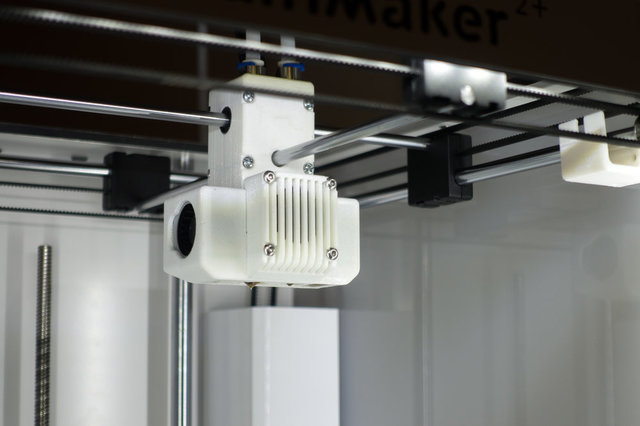
Hi to all The 2016 year had inspired some of us in 3D field, we are always looking to improve our jobs and our equipement. For a long time I wanted to print with ultra-flexible filament without meeting all the difficulties due to the bowden tube on the one hand and the disadvantages of weight and power of the direct drive with the stepper motor on the head of printing on the other hand The flexible shaft is an interesting solution but also has some disadvantages and requires a significant addition of adjustments in a specific software to remove them. I tried to find a compromise between these 3 systems, here are the results Extrusion in direct with the usual stepper motor and using the components of the original extruder or those of the upgrade. The system is quite simple by replacing the Bowden tube by a straight and rigid square shaft between the stepper motor and the feeder, the latter 2 being installed on pivot points to be able to follow freely the X/Y displacements. There is little added weight, +/- 10 grs more on the print head, it's why it is called by Neotko " Zero Gravity Direct Drive ", thanks to him for that and also for giving some good ideas There is absolutely no play in operation, extrusion and retraction have become very accurate by having the full torque power. Printing with very flexible filament has become almost as easy and fast as with the PLA My average retraction setting distance down to 1.5mm (1 to 2mm maxi) Now my average print speed is 60mm / s The other settings remain in accordance with the usual settings depending on the filament used. I improved the ringing by lowering the acceleration values ??and the X / Y jerk, (2500/15 UM2 extended) Depth of 150 hours of test performed with different filament types without encountering problems, the videos shows tests of a hobby car tire wich is printed with the 2.85mm Recreus Fila Flex A82 Shore at 50mm/s print speed and 2mm/30mm/s retractation settings. the Bondtech feeder parts are used here for the 2 print heads, a system with the UM stock knurled wheel is in preparation; some other works future UM stock feeder parts uses in a customized" I Roberti" feeder system


 19 points
 -
Especially for you, here's the post again, so you can give it a second like: Yay, picking is working:
 19 points
 -
I used this function on the old forum a lot, so I could quickly see if there was content that was applicable to me. Is there any such function on the current forum?18 points
-
Hey guys, I would like to share a lever action dual extrusion solution I came up with for Ultimaker 2+. The approach is based on the great effort everyone put into Mark2 and Ultimaker 3. The print head holds two hot ends, which are originally to be installed on standard UM2 head for 1.75 filament. The right nozzle move up and down for nozzle swapping. This compact dual print head can achieve single extrusion print area of 220x223x205, and dual extrusion print area of 202x223x200. Video clips: Files and instructions available at: https://github.com/yyh1002/DXU Credits: Lever lifting mechanism is inspired by Ultimaker 3. The firmware is modified based on Mark2 version of Tinkergnome firmware by @tinkergnome. CURA profiles are modified based on the Mark2 profiles by @tinkergnome and @foehnsturm. Used Mark2Tweaks plugin for CURA by Krys Lawrence.

 17 points
 -
Hello! You may have heard stories about glass plate having one side which brings you slightly better adhesion compared to the other side, or perhaps you have experienced this first hand yourself. Allow me to provide you with some background information and some instructions to figure out which side you should be printing on and which side you should use if you want to add an adhesion sheet. The difference is first introduced during production. When our glass plates are being made, near the end of the production line there is a hardening process. During the hardening process, the plates float on a layer of tin and are heated from above. This creates a difference between the two sides. There are two main factors that ensure good adhesion to the glass plate: wetting and flatness. Wetting is the ability of a liquid to maintain contact with a solid surface. Lower surface tension means better wetting. The non-tin side (i.e. upside during the hardening process) has a lower surface tension than the tin side. Therefore the non-tin side is recommended to print on. If the sticker that is on your glass plate fell off, you can do a simple small test to identify which side is which by placing a drop of water on both sides of the glass. (Not at the same time though). The non-tin side, the side you want to be printing on, is hydrophilic and the water disperses. On the tin side, the water will form a droplet (this side is hydrophobic). If you want to use an adhesion sheet, it is recommended to stick it to this side. Hope this helps! Let me know below if you have any further questions!
 17 points
 -
Yay, picking is working:
 17 points
 -
Public communication simply has higher impact. I'll most likely get called in by management for posting that (would not be the first time) Reasons for making a post like that: 1) Nobody in is right minds makes a 100% custom forum. See the amount of bugs and lack of features? That's why. It's a waste of money really. 2) You have one of the top users of the forums sitting in your office, and you don't even talk to him about your forum change plans. Cura is pretty much born on the forums. I've pretty much lived on forums for a big part of my life. This is not a forum, this is a forums retarded little brother. 3) Communications from R&D to the people who handle communications have been pretty much ignored or misinterpreted. Even when told in the face and emailed. 4) There has been a Cura PinkUnicorn limited beta planned to release on monday. I have NO clue on how we're going to get feedback on that. Normally we handled testing with a hidden subforum. 5) The layout is horrible for information density. 6) Essential features are missing. 7) Bugs everywhere. 8) It's not a "people resist change" issue. Yes, people resist change. I know all about that (see removal of slice button). It's a "we had something that was quite decent, and it's being replaced by something that can only be properly described as a piece of total shit." 9) I'm fed up with this shit. 10) Do not taunt the happy fun rock. Now, most likely I will get some silly promise that they will fix the bugs. Fix the layout. Add the features. But, I'm a software developer. I will tell you it will take a year to get this really sorted out. So I say: Close this shit. Put in normal forum software which we all know that works. Any effort put in here is a waste of money and effort. Effort and money that could be put into other areas. I also ask you all. Do not hold back, do not bite your lip. Tell what you really think! Remember that the forum is there for you, you are not there for the forum.17 points
-
Missed me? I know you did. - As the Ultimaker 3 is now known and will be shipping out towards people and, (don't quote me on this one) hopefully be in the hands of users by FridayNovember. So, I figured I will explain in depth technical details to prevent surprises and improve knowledge for you. I will assume that you are already experienced with certain things from the Ultimaker 2 or Ultimaker Original. I hope this knowledge will help in understand why things work the way they do, and how to get the most out of your new shiny machine. - Other days: Day 2 - Remote access part 1 Day 3 - Remote access part 2 Day 4 - Electronics Day 5 - developer mode linux Day 6 - active leveling GCode If you are reading this, and you don't know what GCode is, you should read up on that somewhere else first. - So. The Ultimaker 3 accepts GCode. Again. Just like the Ultimaker Original, Ultimaker 2, and almost every other printer. However, after much consideration, we decided to break backwards compatibility. So it is no longer possible to run Ultimaker Original or Ultimaker 2 GCode on the Ultimaker 3. We had good reasons for this, during testing we discovered it was quite easy to run the wrong GCode file and thus get bad/unexpected results, which resulted in wasted time and filament. This is also a lesson learned from the introduction of the Ultimaker 2 go and Ultimaker 2 extended. Where running files for a larger machine on a smaller machine could go very wrong. (Checks have been build in the firmware now, but for running extended files on a normal 2 this still triggers very late) The header! So, introducing: The header. The Ultimaker 2 already had a tiny header, containing a few lines. The Ultimaker 3 uses a new header format. This header contains a lot more information, and allows the printer to make a better decision on if the print job is suitable for this printer. It also allows us to upgrade/improve this header in the future. - This does mean, that if you use a different slicer then Cura 2, you need to put in this header. Slightly unfortunate. But that's why I kick this "insider" posts off with explaining this detail. However, not to worry, we did think this one trough. - But enough talking, let me show you a header: ;START_OF_HEADER;HEADER_VERSION:0.1;FLAVOR:Griffin;GENERATOR.NAME:Cura_SteamEngine;GENERATOR.VERSION:2.1.99-internal.20160623;GENERATOR.BUILD_DATE:2016-06-23;TARGET_MACHINE.NAME:FDM Printer Base Description;EXTRUDER_TRAIN.0.INITIAL_TEMPERATURE:210;EXTRUDER_TRAIN.0.MATERIAL.VOLUME_USED:2060;EXTRUDER_TRAIN.0.MATERIAL.GUID:506c9f0d-e3aa-4bd4-b2d2-23e2425b1aa9;EXTRUDER_TRAIN.0.NOZZLE.DIAMETER:0.4;BUILD_PLATE.INITIAL_TEMPERATURE:70;PRINT.TIME:474;PRINT.SIZE.MIN.X:0;PRINT.SIZE.MIN.Y:0;PRINT.SIZE.MIN.Z:0;PRINT.SIZE.MAX.X:215;PRINT.SIZE.MAX.Y:215;PRINT.SIZE.MAX.Z:200;END_OF_HEADER That's a whole lot of information. Some information isn't used by the machine, but can still be useful for diagnostic goals. But let me go over each one in a few sentences. - START_OF_HEADER, END_OF_HEADER, these need to be included. Only the lines in between here are seen as the header, if these are missing, then the Ultimaker 3 will flat-out refuse the file. HEADER_VERSION Once again, this needs to be 0.1 for now. When we make incompattible changes we will increase this number. We are software engineers, so we start at 0. (yes, we had a 0.0) FLAVOR And another one of these. This indicates the flavor of GCode we generated. Griffin is the name for our Ultimaker 3 internal software stack. So this flavor name matches this. It indicates which GCodes are used for what. Which I will go on into detail later. Right now, this needs to be Griffin. (captital G) GENERATOR.NAME This field is required to be present. BUT you can fill in whatever you want. It is to indicate which backend tool was used to generate the GCode. In this case, it's the CuraEngine, still called Cura_SteamEngine as a wink to the past. GENERATOR.VERSION Also required to be present, but same as the generator name, this can be anything you want. It's an indication of which version of a slicer that was used. Useful for diagnostic goals. GENERATOR.BUILD_DATE Pretty much the same as the version, but needs to be a valid date in yyyy-mm-dd format. TARGET_MACHINE.NAME Optional field, filled by Cura in this case to indicate which machine was selected. But you can leave it out. EXTRUDER_TRAIN.{X}.INITIAL_TEMPERATURE Used to indicate to which temperature a hotend should be heated before the GCode file is started. Note, leave out all the EXTRUDER_TRAIN fields if you are not planning to use that extruder. This example is a single extrusion file, and thus does not has lines for the 2nd hotend. EXTRUDER_TRAIN.{X}.MATERIAL.VOLUME_USED When the initial temperature is set, this field is required. You are allowed to set this at 0 if your slicer cannot fill it in. Right now, it is only used to display towards the user how much filament is going to be used (same as the Ultimaker 2). EXTRUDER_TRAIN.{X}.MATERIAL.GUID This field is OPTIONAL. Good thing it is, as it indicates which exact material this file is intended for. As we are using unique codes that can indicate brand material type and color it's easier to leave this field out if you are not using Cura. The Ultimaker 3 will then not check if the material in the machine matches the one for the GCode. EXTRUDER_TRAIN.{X}.NOZZLE.DIAMETER A required field. While we only ship with 0.4 nozzles in our PrintCores right now. We did account for having future versions with difference nozzles sizes. A mismatch in nozzle size and slicing is bad, I don't think I have to explain that. BUILD_PLATE.INITIAL_TEMPERATURE Another required field. This one is important. Because heating up the bed takes a long time. Which is why we want to start heating it up as soon as possible. So we can level, and do whatever we need to do in the meantime. The file won't start till this temperature is reached. If you put this at 0, it will wait till the bed is cooled down before the print. PRINT.TIME Used for time estimates, same as the Ultimaker 2. This is a required field. But once again, put it at 0 if you cannot fill it. PRINT.SIZE.MIN/MAX.X/Y/Z Required fields. Used to indicate how large the print is. As you can see in the example, we just put the size of the printing volume in there. You can do the same. This does mean that a file prepared for an extended, even if it's not tall, will not be accepted on a normal 3. - So. So far the header. Most likely there will be questions. The GCodes While the Ultimaker 2 supported a very wide range of GCode commands due to being Marlin based. We did strip out a whole lot of unused commands in the Ultimaker 3. So to make it extra clear, these are the commands you are used to and are still supported: G0, G1, G4, M104, M109, M140, M190, M106, M107, M201, M204, M205, M302, M400, M117 While not obvious at first, the most obvious missing code here is G28. Yes, you are not allowed to home the head or the bed anymore. As this screws with the leveling correction code. The printer is homed before and after the print, so there is no real need to have this in a gcode file. So G28 does nothing. - Other absent codes are the M82/M83, relative E mode. I don't know if there is a slicer that depends on this. Due to some archtectual things in the code, these commands are difficult to support right now. (Note, I think they do something, but they might stop working in the future, or we will fix the bugs related to them) - I did not list T0/T1 yet. They are however, fully supported, they are more supported then supported. They are very important. As they switch between the different hotends. This means these codes activate the lifting mechanism. So if you want to abuse the lifting mechanism (and we have done this) you just need a long series of T0 T1 lines. It is important that the machine handles this. Not only improves it compatibility with other possible machines, but the "bay" in which the switching happens isn't 100% in the same location for all machines and thus is at a calibrated position, which only the machine knows. Fun fact, we've ran this lifting mechanism test for days and days in a row on multiple printers. I think we have machines with well over 100000 lifts and not showing a single sign of wear. This did take a few design iterations, as the first lifting mechanism prototypes wore out in 10000 lifts. I don't know our full testing numbers right now. But we abused the hell out of this thing. - New code: G280 There is a new GCode command we added. It primes the nozzle with whatever priming strategy the printer has. As we are tracking the position of the filament in the nozzle, the printer has better information on how to properly prime the nozzle. You are not required to use this, but Cura does. - Other codes might still work, but are not officially supported, and we could break/remove them in the future. However, let us know what you miss so we can make sure we are not breaking anything. Compression .gcode and .g are the traditional file names for a gcode file. We are still supporting and using those. We are also introducing a "new" format. And it is everything except hip and fasionable. - It is.... .gcode.gz. The real nerds I have to explain nothing now. The rest of you, this is just a gcode file, but then compressed, a sort like a zip file, but then even simpler. This does mean a massive file size reduction. It uses "gzip" file compression, which is easy to do on Linux, and for example 7zip can do this on Windows. The cool part for us, as software, is that we can read a .gcode.gz file in exactly the same way as a .gcode file. We don't need to unpack the whole file, we can unpack it as we read it. So we don't need to store a 2GB unpacked gcode file when we are printing. End result is that we can fit more files on a USB stick, and we require less time to send a file to the printer trough a network connection. Wrapping it up This is day 1. What will I tell tomorrow? We shall see. Feel free to put in suggestions, but I have more then enough topics. - - Disclaimer: Any information presented here could be wrong. I did my best to proof read everything, but it could conflict with official statements and the actual behavior of the printer.16 points
-
Hello all, This subject contains many very usefull links for new users or more advanced users. Feel free to answer with more usefull links, this topic is meant to be populated by the community. Most of the links are about the Ultimaker 2 (and family). Unboxing and first start Unboxing the Ultimaker 2+ Inside the Ultimaker 2+ Unboxing the Ultimaker 3 Inside the Ultimaker 3 Ultimaker 3, using PVA Visual troubleshooting guide English version French version Ultimaker provided tips & tricks Wide range of tips and tricks Maintenance Unclog the nozzle The Atomic method Basic maintenance Replacing the PTFE coupler Dismantle and re-assemble the head of the Ultimaker 2+ Dismantle Re-assemble the head of the Ultimaker 2+ Test the head temperature Some examples of post-processing yout prints Link to forum topic Installation of the Olsson Block on your Ultimaker 2 To swap your nozzles easily! (compatible Extended and Go) Install the Olsson Block on the Ultimaker 2 Change the feeder of the Ultimaker 2 Install community designed alternative feeder Lists Online manual Online manual Manuals and BOM Build manual Source files Ultimaker Original+ Source files for Ultimaker 2Go Source files for the Ultimaker2 BOM Ultimaker 2+ BOM Ultimaker 2 Extended+ Source files for Cura How to install VPN for your Ultimaker 3. User generated. FAQ and Lessonplans for Educators Softwares Cura Official versions Old versions Beta version below official release (use at your own risk) Manual Cura Tips and Tricks Firmware TinkerGnome Modified version to display more information during a print (UM2, GO and Extended) Forum subject Simplify3d Powerfull slicer, lot's of parameter (price: 130€) Simplify 3D Tutorial Kisslicer Keep It Simple Slicer Slic3r http://slic3r.org/ Repetier Host Pilot the printer via USB, visualise the gcode. PronterFace Like Repetier Host OctoPrint Manage your printer from distance with a web application Tutorial to install it on a Raspberry Pi GCodeViewer WebSite to visualise gcode 3D Design Softwares (Free) Autodesk Fusion 360: Very powerfull, lots of features (Free for students, enthusiasts, hobbyists, and startups) DesignSpark Mechanical: Good software for mechanical parts, quite complete. (Free version of SpaceClaim) 123D Design: Nice app simple to use with some interesting features (for example: text extrusion) 123D Catch scan objects with your camera Sketchup: Simple to use with a lot of plugins Plugin to check that the model is waterproof Blender: Complex software with a lot of possibilities, more suited to organic design MeshMixer: Sculpt STL files, cut, join, etc... mainly used for STL manipulation MeshMixer Tutorial OpenScad: Design in a programming language (usefull for parametric designs) TinkerCad: Easy to use Sculptris: Sculpting software MeshLab: Work on mesh files (very complex but powerfull) NetFabb Basic: Prepare and repare STL files for 3D printing Onshape: CAD system with version control and collaboration built in at its core. FreeCad: List of usefull software There are probably other free design softwares feel free to add them below Paid softwares: Cheetah3d: paid but acceptable price (69$) Other softwares Solidworks AutoCad 3dsMax Cinema4D SpaceClaim Inventor Very expensive but worth mentionning! For students there are some very low cost licenses available! 3D Design librairies: Youmagine:Website managed by Ultimaker, a lot of usefull designs, i encourage all of you to post your designs here! Thingiverse: The most popular website, with tons of designs (some good and some totally worthless) MyMiniFactory: Free and paid objects. Good thing about this website is that when you upload something they print it to see if it's worth adding to their content GrabCad: Lots of 3d designs (Not all for 3d printing) Various: 3DHubs: Service to print for others Colorfabb tutorials Designing for 3d printing Feel free to add any usefull link you have or to give any feedback. I will add them to this post. Material providers list[/b]16 points
-
Hey Guys, I got a little bit of time this weekend, so I finished my thing. It's a Fallout Mini nuke -with innards! Check it out. More pics here!16 points
-
Ok, I gave this some thought, and I'm going to do a drastic suggestion; first of all, thank you Sander, thank you "TheDeugd" and thank you to the rest of Ultimaker who tried to improve a forum. I understand the way you wanted to go. Sort of an interactive FAQ, a place where makers and builders and designers and users could find each other, to communicate, to suggest ideas and to work together. so far, some things are great, some things are not. the path you have chosen, to take a real forum offline, to wait for a week, then bring something partially back online (still missing access to PM's and access to portions of the old forum), collect feedback while live and improve on the go, is not one that works for me. I thought the old forums where bad. the search sucked, in Internet Explorer, half of it simply did not work, some portions misbehaved but overall, it worked. it was an experience that could be improved. instead of improving, you've chosen a path of change. Remember the old saying.. change is good as long as everything stays the same.. You could have moved to new software while keeping the old look and feel then making improvements. A path that is very common amongst many companies and very successful. You choose differently. Once again, I certainly don't want to sound ungrateful, but I have a very simple but drastic suggestion: Please host a "real" forum. buy Vbulletin. buy any software. use open-source I don't really care as long as it's something trialed and proven. Give your community what it wants.. give the people bread and games. keep this and keep improving it. once it's done, and this is not an overnight fix I suppose, then start integrating things. For me, this is not working. Looking through the community I am not the only one. I have to go through a lot of effort to help other people. for free. I have to login every single time. I have to wiggle my way through the weird interactions. I can't really attach pictures without a lot of pain. I feel that halfway through a reply when something doesn't do what I expect it to do I just close the window thinking "oh fuck it". Honestly, I hope it's just me. I hope all the other people that were helping out feel very different than I do and they love this new interface and new forum. If not, more people will start closing windows. Í'll check back in a month or so if I feel more at home till then, I'll just be a vagrant16 points
-
Hello there, do you also love Cura but sometimes get lost in all its beautiful settings? In our knowledgebase on Ultimaker.com we have dedicated many articles explaining how those settings work. So if you find yourself wondering how a certain setting works or if you just want to learn more about what Cura can do, visit this link; Cura settings explained. We put a lot of effort in writing these guides so let us know what you think! Looking forward to hear from you! edit by gr5 - the above link doesn't work anymore. I'm not sure what it linked to but maybe this: https://support.makerbot.com/s/topic/0TO5b000000Q4w3GAC/cura-print-settings15 points
-
Hey guys, thanks to the talented 3dlabprint.com team I was able to print my first rc plane on my UM2... It flies absolutely brilliantly! Challenging but fun print!15 points
-
Ive made this automata as a birthday present for a good friend of mine. Its called "Flight of thoughts" It function as follows: First a gear is selected, high or low, which determines flight speed and rotational speed of propeller. Then the user determines the flight plane by actuating the control stick And lastly the motion is formed by turning the crank. The plane can then be controlled in flight by the control stick. The design uses a swashplate design to give path, which both rasies and lowers the plane, aswell as choose a fitting nose attitude (pitch). The gears and links are merely for control and actuation. Pictures: Overview Slight other view Plane is loosely basen on a fokker DVI. from ww1 Control stick Crank and gear selector Machine declaration (im an engineer afterall XD)


 15 points
 -
Difficulty level High Warning, this isn't a easy trick if you don't know every aspect of S3D. And I mean, 'every'. Hi guys,! First, the images... Basic Elements to make this Trick & have cool toplayers (sometimes perfect) - Create a process that REprints only at the height of the last toplayer - Adjust the settings so it doesn't extrude, and it things that his nozzle it's 0.25 size (play with this from 0.25 to 0.35). This trick will make that the nozzle (0.4 for this example) will do MORE passes on the same places, making it a better and smoother sanding. - Adjust the speed of this new process so it's done really fast. Best results so far where at 100mm/s, I had some weird events at 150mm/s and at 70mm/s the speed it's too low and might affect the finish. - You must remove top/bottom layers, set the process to 100% infill and play with the infill angle. - Infill angle of the process MUST occur on the oposite angle of the real print top layer angle. - Extrusion rate of the sanding process must be 0 or 0.02 (it's the less amount s3d allows) What will happen? It will 'sand' the top layer with the nozzle, removing the lines of the extrusion, making the print look much more 'natural' and (ONLY TESTED ON PLA) on PLA it gives a matte (or gloss if you play with the temp/speed & other things...) finish. If you don't know S3D from A to B this will sound like an alien language DOWNLOAD at youmagine my Example in FFF S3D (Factory file with the cube test) Neosanding ready to see how works. https://www.youmagine.com/designs/neosanding-better-toplayers-finish WARNING - The starting/ending Gcode it's the one I use on my machines, IT WILL 100% make the hotend crush with the bedclips, YOU must change it to your machine. If you didn't read this, sorry it's your problem. Also filament size, settings of the normal process, all, it's customized to my UMO+ with 1.75mm, FatIRobertI Bondtech, UM2+ hotend with custom fans. So EVERY setting will need to be readjusted. Disclaimer: I share this so users with basic know-how can understand the concept, I take ZERO responsibility if you didn't read this before using the FFF on your printer. Ok... The first thing to learn to do this trick it's this... Process ORDER DO matter. So... If you have a process (normal print) and the top layer gcode renders 'after' the toplayer sanding effect, then you need to a) Copy/Paste the process (this will make the copied process to pop on 'last' position. b) remove the copied process. Use this method to realign the process up/down as needed. It's the only way to make S3D does the effect just when you want it, and that's just after printing the real top-layer. Edit: Just found out a faster, and easier way to force S3D to do the sanding process after the real print process. If the real print it's done at 0.2000 layer height, then make the Sanding process have 0.2001 layer height. Photos of the basic stuff to have a good control of See that the sanding process it's before the print, this it's unintended. It doesn't need to be group, but weirdly enough it did work. Sometimes Process order won't look this neat, but 99% of the time the sanding process must be just before the real print process. Why? No idea. As you see extrusion it's set to 0.02, extrusion width 0.25 to make more 'sanding' and retractions are off but for big dripping systems (aka 2.85mm or high temp) it might be good to use retracts. The angle of the top layer done by the sanding process, since it has no 'top layer' or 'bottom' it's done by changing the angle of the infill. Remember the object must has 100% infill and NO toplayer or BOTTOM. Old S3D 2.0 did allow to change the top/bottom angle, but 3.x doesn't, so this it's the way to trick it. Since it has no perimeters, you need to increase the outline overlap to at least 60-70%. 99% does work, but might leave marks on the perimeters. If you use 'perimeters' to make cleaner edges, remember to lower this to 40 or so, it's good that it goes beyond the normal area, but not too much. Play with this, each model might need readjustments. Most and most important. On your sanding process you must choose where it happens. Otherwise it will the full object... and.. well, that works too btw, but it will make your print sooo slow and will create gabs of underextrusion on some places Cura? I think to do this on Cura it might need a lot of tricks, you can't make each top layer for each process, and if you mix this and plugins you might just go crazy. I hope @nallath like this and he or other guys make a Toplayer Sanding Plugin to replicate this hack. It works, and works everytime, but it has a few issues that need to be controlled. - It might cause under-extrusion when it goes back to print. I found that the first perimeter printer after doing this effect had a slightly bit less material, no biggie, didn't affect the print. - On high dripping materials this might not work or create mixed results. I did this for PLA since it's the material I use 99% of the time. I don't think that this will be a good idea for materials like wood (easy to scratch) - On very easy to scratch materials, like carbon, wood, etc, YOU might need a Prime tower object to reload the material that did drip. - The temperature of the nozzle while it's doing this will affect the finish. I did some crazy experiments before this playing with z, making the nozzle cooldown, etc. It was ok, but also a bit dangerous because the print could get knockoff, and ofc sometimes the amount of material on the nozzle was too much. - Playing with the Z offset of the sanding process you can actually 'compress' the material, did some crazy tests with this with semitransparent red from colorfabb and was quite cool, but again, that's up to your experimentation. It doesn't work for me, how do I do this!!?? Sorry this it's a really advanced hack with process, isn't something to click-print, and need's a good understanding of how process work and settings, and grouped things share settings, etc... Have fun with process!!


 14 points
 -
Here's some first impression feedback... Mobile > I really like the ability to go to the last page of the thread on the mobile version of the forum! wanted this for a long time.. Readability > After a few hours (ok I will give it more time..) I think the readability is a lot worse than it was before, not sure whats causing it, maybe the overkill in colored dots, or the huge spacing between everything... think my main wishes for now would be; - remove the repetition of the first post on every page. (also terrible on mobile, to much scrolling) - add the "go to page numbers" also on the top of the page. quick access; I used to get a quick overview of whats new by looking at ONE start page, I would really like to get this back, please add the last post & date to every topic on the main overview page. Search > I used to get good search results with advanced google (search in the forum domain) I hope this is not permanently damaged now its on a new domain. Tried the "in site search" , first impression results are crap, hope this will improve over time but I'm afraid the history is gone. Please add a "back to forum" button on the top of the search result page. Please let me filter out undesired languages in search. General > It seems some web / youtube links work and some don't ??? Assume you'll fix it also on old pages ...14 points
-
I've been following this dual extrusion discussion for some weeks now. The more I read the more I get the impression that the usual approach doesn't fit for UMs at all. Too bulky, too heavy and so many well known flaws, like oozing and having the second nozzle knocking down prints. It simply makes no sense to me to carry around a second hotend all the time. So I suggested independently moving heads or a tool changing mechanism like CNC machines are using. I couldn't resist ... Just a proof of concept right now but way better then I expected: 0.0 positioning play within the mount, more than enough clamping force, no additional actuators needed C'mon, if I can get this far in two days ...14 points
-
Ok I admit it, I didnt 3D print this. BUT...i certainly played my part it making Her ultimaker has one more fan to add to the list. Hello World
 14 points
 -
I have created a plugin that lets Cura access HID mouse devices such as the 3Dconnexion Spacemouse. It's called RawMouse because the plugin interfaces directly to the raw device without the aid/hinderance of an operating system driver. It's not a sophisticated all-singing, all-dancing interface, it simply converts the HID mouse commands into the equivalent 2D mouse commands. It has been (vaguely) tested on Linux and Windows 10 and it should also function on MacOS (10.13 upwards). For a quick install, unzip the latest RawMouse.zip from https://github.com/smartavionics/RawMouse/releases into your plugins directory, connect your Spacemouse, and start Cura. The usual weasel words apply, it's supplied with no warranty, YMMV, etc. All feedback is welcome. Either comment in this thread or open an issue on the github page.13 points
-
Recently I started experimenting with cutting out vinyl stickers with my Ultimaker 2 and figured I'd share my method to save time for others if they want to do the same thing. Using a 3D printer to do this is nothing new, it has been done plenty of times before. But this is how I did it. Get comfortable, this is going to take a while. I've tried to make it as easy as possible to do but be prepared to do some tweaking and experimenting along the way. What you need (if you want the software to be free): - A holder and knives. The one I got was this: "15pcs 30°/45°/60° Degree For Roland Cutting Plotter Vinyl Cutter BladeHolder" http://r.ebay.com/STTdJx - A printed holder (see zip) - Some vinyl: Available from arts and craft stores, ebay, sign makers etc. I got a random piece from Ebay to try. - Vinyl transfer tape (or in my case, some random blue painters tape from tesa I had in the junk drawer that worked well) - Inkscape to create your design: https://inkscape.org/en/ - dxf2gcode: https://sourceforge.net/projects/dxf2gcode/ - Better Better DXF Output for Inkscape: http://tim.cexx.org/?p=590 - Pronterface/Printrun: https://github.com/kliment/Printrun A slightly modified version of the DXF exporter and dxf2gcode with my current settings are included in this zip: http://www.theintarweb.net/ultimaker/vinyl/um2_vinyl_cutter.zip Setting up your hardware Print out the little mount that is included in the zip. It was made quick and dirty, but it works well enough. Attach it to the head using the screws that hold the fan shroud in place. Install a knife into the holder and adjust the amount it sticks out so that it just barely cuts through your vinyl, but not through the paper backing. It's important to get this distance right or you will either not cut enough, which means you can't remove the excess vinyl, or you'll cut too deep and ruin your knife (good thing the knock-offs are cheap ). As you can see in the image, we're talking a tiny amount that the knife is sticking out. Try the setting on a piece of vinyl by pushing the holder up against the vinyl and dragging the knife in a circle. Try peeling the circle out. It will be obvious if you're cutting too deep or not deep enough. Adjust accordingly. I also recommend using some fine sandpaper to polish off any sharp edges on the front of the knife holder as it will be dragged across the vinyl. Push the holder into the mount in your printer and use a short M3 screw to secure it in place. Install Pronterface and connect your printer to your computer via USB. Set your baud rate to 250000. Choose the correct port (you can find that in the Device Manger in Windows under the "Ports" section) or just pick one from the list in Pronterface and try connecting until you find the right one. The printer will go *clunk* and the lights will go out temporarily, this is normal. You now have full control over your printer. We will use this program to figure out the correct z-distance for your installed knife. Start by clicking on the homing button (the small house) to home all axes on the printer. Next, move the head into a position where you can get a good view of it in relation to the glass. I like to put it in the middle of the bed, slightly towards the front. You do this with the large circle area of Pronterface. Click the different quarter circles to move the head in increments of 0.1, 1 or 10mm in X and Y. Now it's time to raise the bed. In the lower right corner of Pronterface there's a small field where you can put in GCode to be sent to the printer. Type in "G0 Z20" and hit enter. The bed will now move up and stop 20mm from the tip of your nozzle. Now use the buttons next to the quarter circles to raise the bed further until the tip of the blade is just barely in contact with the glass. Type in "M114" into the little box and hit enter. The printer will now give you the current Z-height (in my case it's 1.7mm). Write this number down. Optionally you can also print out "um2_bed.pdf" from the zip and put it underneath the glass. It makes it easier to position the vinyl pieces. Setting up and using the software Start by downloading and installing Inkscape. After the installation is done, unzip the contents of "b2_dxf_output.zip" directly into your "[installation directory of inkscape]/share/extensions" folder. You will be asked to overwrite "simpletransform.py", this is normal. Unzip "exe.win32-3.4.zip" to a place of your choosing. I've included a file called "decal_helper.svg" in the zip. You can use this file as a base to make things easier to position. Make sure that any shapes you draw are not on the "IGNORE:HELPER" layer. That layer will be ignored by dxf2gcode. Also make sure the design is within the red outline. When you're done with your design go to File->Save a copy. Under "Save as type" select "Better Better DXF Output (*.DXF)", this is the extension you installed earlier. If things go according to plan this will save your file as a DXF that dxf2gcode likes (it chokes on the default exporter that is built in by default in Inkscape). Now open up dxf2gcode and go to Options->Configuration. You probably want to start by changing the two paths shown on the top right as you will not have those folders on your system. It's not strictly necessary to change it, but it makes things less of a hassle when importing and saving files. Next, go to the "Machine config" section and put in the value you wrote down earlier in the "Final mill depth" box. Yes, this means that the gcode produced will cause the printer to raise the glass so that it's almost touching the blade when cutting. BUT, we set the blade in the holder so that it only peaks out enough to cut the vinyl, so as long as you have vinyl under the holder, the "springiness" of the gantry will let holder move up ever so slightly and the knife will cut to the perfect depth. Hit "Apply" and close the settings. Now it's time to load the dxf-file you created via File->Open. It may take a little while for the program to process your file. When it's done you'll get a warning about some elements being too short, just hit OK. You should hopefully be looking at something like this now. In this screenshot I've zoomed in on a corner of a path to show the drag knife compensation that dxf2gcode does. This is one of the reasons I picked this program, the other being that it's free. As a last check, make sure that "Z final mill depth" matches your value when clicking on one of the shapes. Now it's time to export the file via Export -> Optimize and Export Shapes. We're almost done. Cut out a piece of vinyl and attach it to your bed. This is where the guide lines in my Inkscape helper-file and the printout comes in handy. I like to put a piece of tape on all sides of the vinyl to make sure it stays firmly planted to the bed. You can probably get away with less, but tape is cheap. Switch back to Pronterface and open the file you just created. Finally, it's time to try your first cut. If your printer has been turned off since you last used Pronterface, remember to home the machine first with the little house button. Hit the Print button and keep a finger on the power button of your printer in case something goes horribly wrong. If all goes well you should now have a freshly cut piece of vinyl ready to clean up and get ready for application. Remove all the excess and then apply some vinyl transfer tape. Use something like a credit card to really push the tape onto the vinyl to make sure it sticks properly. If your design is a bunch of small shapes (text for example), I recommend putting the transfer tape on right away, scrub it down really well and then carefully peel it off, this will lift the letters from the backing (with some patience and a helping hand from tweezers/scalpel). I found this to be a lot easier than trying to pull the excess away from around the text. Did you make it all the way down here? Sweet!


 13 points
 -
This is a project by a group of community members which was also involved in the Mark2 dual extrusion upgrade. More precisely, it's me coming up with an outside the box approach / weird idea for a certain unresolved problem. Smart people like @gr5, @Anders Olsson, @Dim3nsioneer, @rooiejoris throwing in ideas and @tinkergnome who implants the stuff into firmware. My impression of the current state of development when I started this was as follows. There have been filament monitor projects since the beginning of reprap. Only very few made it to some kind of product state, like the one by Aaron Tunell. Manufacturers like Prusa and others recently introduced some kind of filament monitors, with mixed success / reliability issues. The Duet3D guys set their hardware research (laser-based and rotating) on hold because they were experiencing inaccuracies of +/-20%. Well and then there was Ultimaker ... until yesterday with the S5 All these efforts have been or still are struggling to fulfill the most important objective: NO FALSE ALERTS. Otherwise any filament sensor would quickly render itself useless. What we want to achieve Objectives, the obvious part: zero false alerts detect filament runout ("nothing there") detect filament grinding ("nothing/very little moves") Objectives, the challenging part: detect first layer issues (see video below) detect when real flow leaves a certain safe process window and starts to compromise part quality (first, inter layer adhesion will suffer, then classical under extrusion will be visible) and try to counteract, that's where the real fun starts ... Current state of development We chose an encoder and there's a reliably working prototype for an easy to attach external flow sensor, mounted to the entry side of the feeder. Resolution is in the range of 0.015 mm. It's integrated in Tinkerware with a dedicated menu and we (well, he) implemented a gcode command: M591 T0 S1 E0.5000 L0.01695 R35:130 A0.3 P100.00 I leave the parameter interpretation as a little quiz here. Right now I'm working on a modified design which, besides the encoder, doesn't need some parts which cannot be printed and are in the +30€ range to have them manufactured. But most likely some parts will still not be FFF printable. How can I get this? First give us some more time to test and evaluate. If everything works like intended we might proceed like with the Mark2 project. If we should offer this as a product I'd expect a price tag between 70-100 €. And the UM3? That's the BIG question. Like @Daid recently stated their main market is already different. And indeed, has anyone seen any kind of (hardware) upgrade for the UM3 so far? Feeders are the same, mechanically our sensor fits. Electronics, not sure. Ultimaker originally wanted to use a serial interface on the UM3. For the UM2+ we simply connect the sensor's quadrature output signal to free I/O pins, there are enough left (4) for two sensors for a Mark2 dual extrusion UM2. Ultimaker won't do anything to support a sensor on the UM3. Anyway, if a large number of UM3 users would show interest, they might at least not impede a development ...13 points
-
How can the very latest, cutting-edge design software combine with a 5,000 year old manufacturing technique to deliver outstanding weight reduction opportunities? Designing for light-weight parts is becoming more important, and I’m a firm believer in the need to produce lighter weight, less over-engineered parts for the future. This is for sustainability reasons because we need to be using less raw materials and, in things like transportation, it impacts upon the energy usage of the product during it’s service life. Lighter products mean less fuel to move them around, which can make our fossil fuel reserves go further, or make more efficient use of the renewable energies that we’re now beginning to adopt. Generative Design (GD) is the very latest design software released by Autodesk and is now included in Fusion 360, which is at the heart of their "Future of Making Things" strategy for Design and Manufacturing. It changes the way we design things and can deliver very efficient designs that deliver structural performance with optimised use of material. The aerospace industry is expected to be one of the early adopters of this technology because in that industry the cost and environmental savings from improved fuel efficiency carry the greatest rewards. Also, I see interest from the automotive industry for the same fuel efficiency reasons, but in the long term the drive for lighter weight parts could benefit many industries, even those outside of transportation. Another example of the benefits of lighter weight alongside reduced material usage is that shipping costs for parts reduce as their weight reduces, which can therefore also deliver cost efficiencies. GD is targeted initially at metal parts where the biggest opportunity for light-weighting exists. The complex forms it generates though often means that parts conceived in this way cannot be made with conventional manufacturing routes. They therefore need to use Additive Manufacturing (AM) techniques to produce them. The route of using high energy, laser-based AM to do this comes with associated high costs because of the specialised set-up knowledge required together with expensive processing, and post processing, to deliver a quality-assured part. This project explores the possibility of a more cost-effective route to a metal GD part which, even though at this stage may be just used for a small quantity of evaluation prototypes, can act as an enabler for understanding the potential that GD has to offer. This is the baseline design for this project. It is an aluminium bracket design similar to those used in aerospace applications to mount control surfaces, and in this form has not been optimised for weight. This design would weigh 383 grams in the intended material, aluminium A356. After processing this through Generative Design in Fusion 360 it’s time to review and evaluate the many alternative design options presented and decide upon the design that is considered the most appropriate taking into the other factors that have an influence on design selection such as manufacturability, aesthetics etc. This was the design option chosen for this part and Fusion 360 was used to create the final version of the model. The bio-mimicry that’s evident in most of the designs created by GD is interesting to see, in this case the design of the part can be seen as essentially a swept I-beam (which engineers, especially those in construction, are taught is a strong section), but with tendon-like attachments back to the mounting points to carry the tensile loading that’s created by the applied loading conditions What GD does is to turn the standard design workflow that we’re familiar with on it’s head. Traditionally we design a part and then stress test it virtually to determine if it fulfils the required structural performance. Any failures seen during this process require an iterative loop back to the design to correct them. With GD the stress analysis is a core part of the design synthesis, and happens as the part design iterates, which means that the output at the end should meet the requirements of the intended loading requirements. The software is searching for an optimal solution where the stress is ideally evenly distributed across the part as can be seen above. To prove that everything is good with the finalised design this part has then been virtually tested again in Fusion 360 to confirm that the original loading requirements are still met So we've created our lightweight part design, and maybe now we need to produce that in aluminium A356 to do some physical testing, but don’t want the expense of using a metal AM process. What follows is a way of achieving this where FDM 3D printing can play a role as an “enabler” to help create the final parts in conjunction with a very old (if not ancient) manufacturing technique called investment casting. This technique is 5,000 years old according to Wikipedia. The company involved with casting this project is Sylatech who have been using Ultimaker 3D printers as part of their process for investment casting of prototype parts Sylatech took the .stl file of this model and used it to create a 3D print of the part on an Ultimaker 3 in PLA. This PLA part was then used as the pattern in the investment casting process where it is submerged in plaster under vacuum conditions to ensure that all air is excluded from the mould and creates an accurate reproduction of the surfaces of the part. The picture below shows a display box which demonstrates the set up of the 3D printed parts partially encased in plaster. Once the plaster has hardened the casting box is put into a furnace at very high temperature in order to burn out the PLA, leaving behind a cavity into which molten aluminium can be cast. After solidification of the metal, and cooling of the mould, the plaster is broken away from the parts, and then they can be quickly and easily removed from the material feed gate resulting in these aluminium A356 versions of the PLA original. The final part weighs 122 grams which is a weight saving of 68% over the original baseline part, which shows the potential that GD has to make significant reductions in weight and material usage. Using this method we now we have an excellent quality physical part made very quickly in the final intended material in order to commence some physical testing.This is a different route to get to that physical test part in metal at a fraction of the cost of having it metal additively manufactured. It also shows how a brand new, cutting edge piece of software that only became available in May 2018 can combine with FDM 3D printing (which many people still see as a new technology even though it’s been around for over 20 years) and a 5,000 year old manufacturing technique to deliver potentially huge benefits in weight and material usage. Using the investment casting route in this case study is why I chose the title for this article, and shows that we can effectively go “Back To (Deliver) The Future”. Do you see the need for lighter weight parts in what you do, and can you see the potential benefits of using Generative Design and this method of producing metal parts? I'd welcome comments, suggestions, and discussion about any aspects of the above article, the next steps that I'm looking at are how this process could scale up to batch production of the parts using 3D printing techniques that could support low volume production quantities


 13 points
 -
I think I figured it out. Cura 4.0.0 now has a new feature where you can select different number of cooling fans. I looked at the gcode exported from cura 3.4.1 and the gcode from cura 4.0.0. I noticed the M106 command was exported as M106 S255 P1. I compared this to the gcode exported from cura 3.4.1 which just had M106 S255. I first tried to modify the gcode to have M106 S255 P0, AND THAT WORKED Later in my investigation I noticed in the "Machine Settings" under "Extruder 1", there is a new setting called "Cooling Fan Number", by default it was set to 1, hence the "P1" reference in the gcode. Change the option under "Cooling Fan Number" from 1 to 0. After that I saw cura exported the gcode as before M106 S255. I popped in sd card and it seemed to solve my issue. I am sure maybe in the Marlin configuration you could change the fan number as well but this seemed to fix my issue. Hope this helps!
 13 points
 -
Over the last few of months (time flies when you're waiting on parts sent via China Post), I built a UM2 clone using Misumi aluminum extrusions. It started as a project to teach myself AutoDesk Fusion 360 but it's turned out to be a great printer. I imported the UM source solidworks files in A360, dropped the walls (frame), and added extrusions and support parts so that all original UM2 hardware is supported. The entire guts is 100% UM2 with all hardware untouched as far as position/size. I used the UM2 assembly manual to build the gantry and to get other wiring clues. I've published it to YouMagine with pretty decent instructions and a BOM. If you have questions, just let me know.
 13 points
 -
13 points
-
With great pleasure, I present to you my contest entry. I hope you enjoy watching it as much we enjoyed making it. Scene was taken in a single shot, timed to match the sound track. The video has not been altered (e.g. the video has not been stitched together, sped up, slowed down, etc.). The Ultibot was printed on my Ultimaker 2 from the file provided, scaled up 1.45 in all directions. I did not make any modifications to the Ultibot design. I designed the conveyor and crank assembly with Fusion 360, and printed it with the Ultimaker 2. If there is interest, I can upload my conveyor and crank assembly. With some experimentation, I found that the Ultibot likes walking on copy paper, so this is the material of the conveyor belt. The crank belt is an elastic hair band which runs on crowned self-centering pulleys. The conveyor includes a support plate that underlies the conveyor belt to prevent sagging. The scenery is a 3D paper cutout work of my own design. Everything was cut out by hand, and assembled with double sided foam tape which provided some separation between the paper layers for a 3D layered look. The foreground and background elements were attached to lengths of cardboard and pulled across the camera's field of view. The foreground is 50% longer than the background to provide a parallax effect. The boat is mounted to its own cardboard, and moved independently of the foreground and background. To execute the scene, my wife cranked the conveyor belt, pacing it to keep the Ultibot centered on the belt, and also took charge of the boat. I moved the foreground and background elements, pacing their relative speeds to align the transitions between the terrains (hills, water, desert, and urban). The title screen was prepared in Photoshop, and the video was produced with Lightworks 12.13 points
-
Mark2 is an asymmetrical multi-extrusion upgrade for the Ultimaker 2, based on Foehnsturm's magnetic tool changer. It offers some unique features compared to conventional approaches. Keep it smart and simple The Mark2 upgrade doesn't require to modify or even disassemble the well-working single extrusion setup. Instead it adds a detachable second extruder. This leaves you with several benefits. Powerful - print quality on par with eg. the UM3 or BCN3D Sigma Flexible - use whatever you want: Olsson ruby, 3Dsolex block / nozzles, ... Cost-efficient - all you need is a second drive train, some magnets and screws Simple - all tried-and tested standard components Smart - Z-offset managed by firmware, calibration wizards Open & scalable - a non-extrusion tool head, a 3rd extruder ... all possible Mark2 is an Ultimaker community project, we don't offer a complete kit but we can help you out with a package, including all the parts you need, besides the second drive train. See it live Probably the best way to get an impression of the usability and print quality is to watch a few videos. https://www.youtube.com/watch?v=PLeNzDYMnqAqIeZHWU9iOWnj_2OaemupQG Full Cura 2.5 integration Mark2 comes with a set of Cura definition files and can be added as a pre-configured printer. Tried and tested Mark2 setups have been printing for more than 5.000 hrs now, which equals more than 500.000 tool changes. Beta-testers and co-developers include well-known guys here like Tinkergnome, Ultiarjan and many more. The Mark2 website ultimaker-mark2.com is the place where you find all the information you need for doing this upgrade. ... and The Mark2 Dual Extrusion Project Contest is still running.12 points
-
I'm working on a new plugin that adds a simple measuring aid to Cura: In its current incarnation, the tool lets you pick (and drag) two points and shows the distance between these points. A test-version can be downloaded here: MeasureTool Download the file and drop it onto the buildplate in Cura as if you were opening a 3d model. Then restart Cura as instructed. The plugin is now available in the Marketplace.
 12 points
 -
A small update, we are doing a lot (A LOT) of testing to optimize every single part, from print time to assembly to tutorial videos. Is quite a lot of work, but so far we are on a really good point print quality. Ofc like any beta testing we found stuff to improve. Right now we have 3 versions and we are testing every single part as much as we can. Basically from the first design to the new we had 5 versions, and atm the last 3 versions are under stress testing. Also please, if someone has a REALLY difficult print, something that requieres finesse and precision, I would like to print it and test it to see if there's any weak point. Ofc if someone want to share it with me and keep the files form being public that's ok too. I would really like have an architecture file or something really challenging apart of voronoi and very thin walls. Also after talking to @bondtech and we just got 2 ideas that could be really interesting for the guys like us that want as much precision as possible from the extrusion, up to the decimal points of estep calibration for each kind of filament. Very interesting stuff, we will publish more when we have more tests of this ideas.
 12 points
 -
successful proof of concept !! the first print is done...


 12 points
 -
Are you one of the many users who need to stop Cura from using the whole CPU as soon you drop a STL to slice? Do you want to enjoy the freedom of being able to change settings without the constant autoslice bullying you? Very easy: Quick tutorial to stop Cura from autoslicing at every single change. How to: - Change Flow to 1% - Done! How to restart autoslice - Change flow to 100% - Done! Easy enough? So easy I made a video, because this deserves it! a 3 Minutes video! That's how much I enjoy this trick Note, yea my English is NO BUENO. I know Press Like on this 'idea' to show that you like to be able to stop Autoslice! (or don't if you love to use more CPU than necessary and you don't care about energy savings or the poor Rain Forest!)12 points
-
Been playing around a bit with Colorfabb HT clear, trying to get it as clear as possible. This is the latest print I made and I'm pretty happy with this one. As an extra experiment I also tried "suspending" something inside the print, sort of like those 3d laser etched crystal things you can get. Post processed by wet sanding (240-320->600->1200), followed by polishing paste, followed by a polishing wheel. I tried some clear coat in a rattle can as well but I think I suck too much with one of those, I got better surface clarity with elbow grease I also had to baby sit the print and pause it a few times to clean off the nozzle. HT loves sticking to the nozzle, burn into black goo and then drop into the print.12 points
-
Here my project has been growing over the last 2 weeks. I first made sections with one glass and I coupled them And now it is the final size and very difficult to move:) And here it belongs as you see the station still needs a lot of work But it is getting somewhere. And difficult to put it on my camera it is getting to big...


 12 points
 -
Hey guy's. Its been a while since I posted anything on here so I thought I'd share this with you. Although this is my first post in a long time, I've still been lurking in the forums and I have to say I'm blown away by some of the stuff you guys have been printing. Seriously inspiring stuff! I've just launched my new website so head over to see some 3D renders of this guy leohaslam.com Cheers

 12 points
 -
I helped to print in 3D a wonderful job! Dmitri Dubyaga my friend and Colleges. Meet brotherbear-of-steel, #fallout #falloutstyle he created the 3D model within 14 days. I printed it for 36 hours on 3D printer #ultimaker2 and pla #rec. 5 days later, Dmitry painted by hand with acrylic paints


 12 points
 -
I was looking into a way to occasionally print Ninjaflex or other real flexible materials (85A) There's no way you'll be doing that reliable with a bowden setup (ok, I've seen people using oil in the bowden but nahhh), so I compared a quick and dirty direct drive conversion on an Ultimaker2 head (tested on my DIY GO) and on the ultimaker S5 **** first a warning, Ultimaker does NOT want you to open the S5, it contains an open style high voltage power supply, so it's DANGEROUS!!!, also the electronics can be damaged and I'm pretty sure you loose your warranty. **** I used two materials for testing, Extrudr TPU Soft and Ninjaflex, both 85A. I used the regular feeder from the UM2+ , combined with a pancake stepper motor (LDO-42STH25-1404MAC#190920) this stepper is less than half the weight of the normal stepper. I had to cut some length of the shaft to make it fit. The stepper has a different # steps per rotation and as it's impossible to change the steps setting for the S5 on one feeder it needs compensation in flow (200% flow = 100%) Obviously the result is a crazy top heavy setup, but if you just want to print an occasional gasket it should be fine, specially since you need to print materials this flexible very slow (15 mm/s) anyhow. On an Ultimaker2 the extra weight is enormous, on the S5 not so much as it's very heavy already anyhow. The nice thing is you can see into the feeder so during testing it's easy to spot when the feeder can't cope if you try to speed it up to much. If something goes wrong it's mainly during the first few layers, so watch them... otherwise you'll spend a few minutes again taking the feeder apart... To validate the basic setup I printed regular PLA on both converted machines, to make sure the setup (including changed steps/flow due to different motor) was correct. On the UM2 head the ninjaflex was pretty easy to get working, i managed to print with constant and reliable extrusion using a 0.4 nozzle. The materials prints best around (I tested with 0.15 layers) Flow : 110-115 % (with feeder tension set to lowest point) Temperature : 210 c Speed : 15 to 20 mm/s The easiest way to test temperature and flow is by printing simple cilinders, foir the S5 you can use the "tune" menu to play with values on the fly. Getting ninjaflex to work on the S5 proved to be more difficult than on the UM2, at the same settings using an 0.4 mm nozzle prints failed all the time, it seems the CORE, is much more of a challenge that a UM2 setup. I blame the longer filament path, and the metal tube of the core. Only when I changed to the 0.8 nozzle and the CC0.6 I was able to get reliable results. My main S5 tests are with the CC0.6, atm my best results are with the following settings; The S5 levels pretty close to the bed, making every print fail at normal flow rates. Layer height 0,15 Initial layer height 0,25 Top/bottom pattern & Innitial layer pattern ; concentric (avoid lot's of small lines, head vibration) Innitial printing temperature/ innitial layer : 230c Printing teperature : 215c Skirt/Brim flow 140% (= realy 70%, due to the different stepper motor) Innitial layer flow 150% (= realy 75%, due to the different stepper motor) Flow 225% (= 2x the real flow, due to the different stepper motor) Print speed 15 mm/s Innitial layer speed, Skirt/Brim speed 10mm/s Cooling at 100%, start with 20% and let it rise over 10 layers) Turn off the flow sensor (in the settings menu) on the S5, as you're not using that feeder.. Conclusion, even if you eliminate the bowden, printing 85A flex on an Ultimaker S5 is still a bit of a challenge. The used feeder (UM2+UM3 model) and filament path are not ideal. But, usually if you make it past the first few layers, and have relatively simple prints that keep the flow going it's very well possible to print ninjaflex on the S5. I have not experimented a lot with it jet, but I also managed a simple test print using PLA for support on the 2th extruder. the hardware hack; The feeder plate mounts to 3 screws of the head, so you can leave one and the head will stay assembled during mounting. I made a little breakout plug for the left stepper motor on the back of the printer, so I can change between direct and bowden in just a few minutes. I just leave the black mounting plate on the head. In needed to make a hole in the bottom plate for the DIY extension cable. I isolated the plug with hot glue. some side notes; Cura can sometimes create fantastic vibrator g-codes, not nice with this heavy setup, so one thing you can do to prevent this is to change line fill to cylindrical fill, and check the layer preview. ninjaflex openRC wheel, printed on S5 extrudr TPU soft (85A just like ninjaflex) gasket, printed on S5 S5 stl's S5_FlexDirect.zip


 11 points
 -
With the release of the Cura 5.0 beta, a lot has changed in the core of Cura. So much so, that in order to be compatible with Cura 5.0, all plugin need to be updated and resubmitted to the Marketplace. I maintain a number of plugins, and you can imagine that it takes a while for me to update the plugins but also for the Ultimaker dev team to review them. I will use this post to share with you a growing set of pre-release versions of my plugins so you can test them with Cura 5.0 beta. Edit: All plugins are now in the Marketplace, and the prereleases for these plugins below should no longer be used (but will remain available on github) OctoPrint Connection: https://github.com/fieldOfView/Cura-OctoPrintPlugin/releases/tag/v3.7.0-DEV Mesh Tools: https://github.com/fieldOfView/Cura-MeshTools/releases/tag/v3.7.0-DEV Sidebar GUI: https://github.com/fieldOfView/Cura-SidebarGUIPlugin/releases/tag/v4.3.0-DEV Measure Tool: https://github.com/fieldOfView/Cura-MeasureTool/releases/tag/v1.1.0-DEV Z Offset: https://github.com/fieldOfView/Cura-ZOffsetPlugin/releases/tag/v3.7.0-DEV Linear Advance: https://github.com/fieldOfView/Cura-LinearAdvanceSettingPlugin/releases/tag/v3.6.0-DEV Edit 4/23: OctoPrint Connection: https://github.com/fieldOfView/Cura-OctoPrintPlugin/releases/tag/v3.7.0-DEV (updated) Arc Welder: https://github.com/fieldOfView/Cura-ArcWelderPlugin/releases/tag/v3.6.0-DEV Start Optimiser: https://github.com/fieldOfView/Cura-StartOptimiser/releases/tag/v3.6.0-DEV Titlebar Info: https://github.com/fieldOfView/Cura-VersionInTitlebarPlugin/releases/tag/v3.6.0-DEV Automatic Slicing Toggle: https://github.com/fieldOfView/Cura-PauseBackendPlugin/releases/tag/v3.6.0-DEV Edit 4/25: Printjob Naming: https://github.com/fieldOfView/Cura-CustomJobPrefix/releases/tag/v3.7.0-DEV Material Cost Tools: https://github.com/fieldOfView/Cura-MaterialCostTools/releases/tag/v3.6.0-DEV Setting Visibility Set Creator: https://github.com/fieldOfView/Cura-SettingVisibilityProfileCreator/releases/tag/v3.6.0-DEV Printer Settings: https://github.com/fieldOfView/Cura-PrinterSettingsPlugin/releases/tag/v3.6.0-DEV Edit 5/6: Material Settings: https://github.com/fieldOfView/Cura-MaterialSettingsPlugin/releases/tag/v3.6.0-DEV I will update this list with prereleases of other plugins, or when a new prerelease is necessary to fix a bug. To download these prerelease versions, go to the linked page and scroll down to the 'Assets' section. There you will see curapackages compatible with different versions of Cura. For Cura 5.0 you will need to download the file ending with `Cura5.0.curapackage`. After downloading that file, drop it onto the 3d viewport in Cura 5.0 as if you were opening a 3d model. You will then be prompted to restart Cura. You can drop multiple curapackages one after the other without restarting each time if you want to install multiple plugins. If you want to test these updated release in an older version of Cura, please download the curapackage labeled for that version. It is quite early days, and some of the plugins required extensive work to make them compatible with Cura 5.0. Feedback is welcome, either here or in the issue queue for the respective plugins.11 points
-
I'm working on a plugin that changes the new GUI in Cura to be more settings-centric by adding back the concept of a sidebar. If you can't get used to the floating panels in the new GUI, there will soon be a plugin for you. While rearranging things into the sidebar, I am also taking the chance to rearrange some other bits: move X-ray from the Preview tab to the Prepare tab in my opinion it makes more sense to detect/show errors *before* slicing reunite the Open button with the Toolbar Fitts's law suggests keeping distances between small items smaller; I just dislike having UI elements in all corners of the UI. add the same menu and sidebar between Prepare and Preview so things don't jump around The plugin is currently in the state of a proof-of-concept; there is currently no way to switch between the Recommended and Custom sidebar, and there is no way to change the materials/printcores in the sidebar. When all standard functionality is in its new place I'll post a prerelease here before publishing the plugin to the Marketplace. If you can't wait, you can check out the code here: https://github.com/fieldOfView/SidebarGUIPlugin Things I'm considering: integrate the action panel into the sidebar move job name into sidebar move standard view items into view options/legend area The plugin is a spiritual successor to the Compact Prepare Stage plugin, though it was written from scratch with a different end-goal in mind. That plugin will not be developed further. Update: a beta is available below:https://community.ultimaker.com/topic/26014-sidebar-gui-for-cura-40/?do=findComment&comment=229800
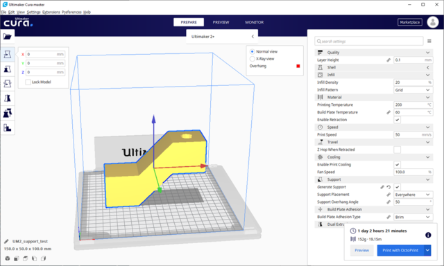 11 points
 -
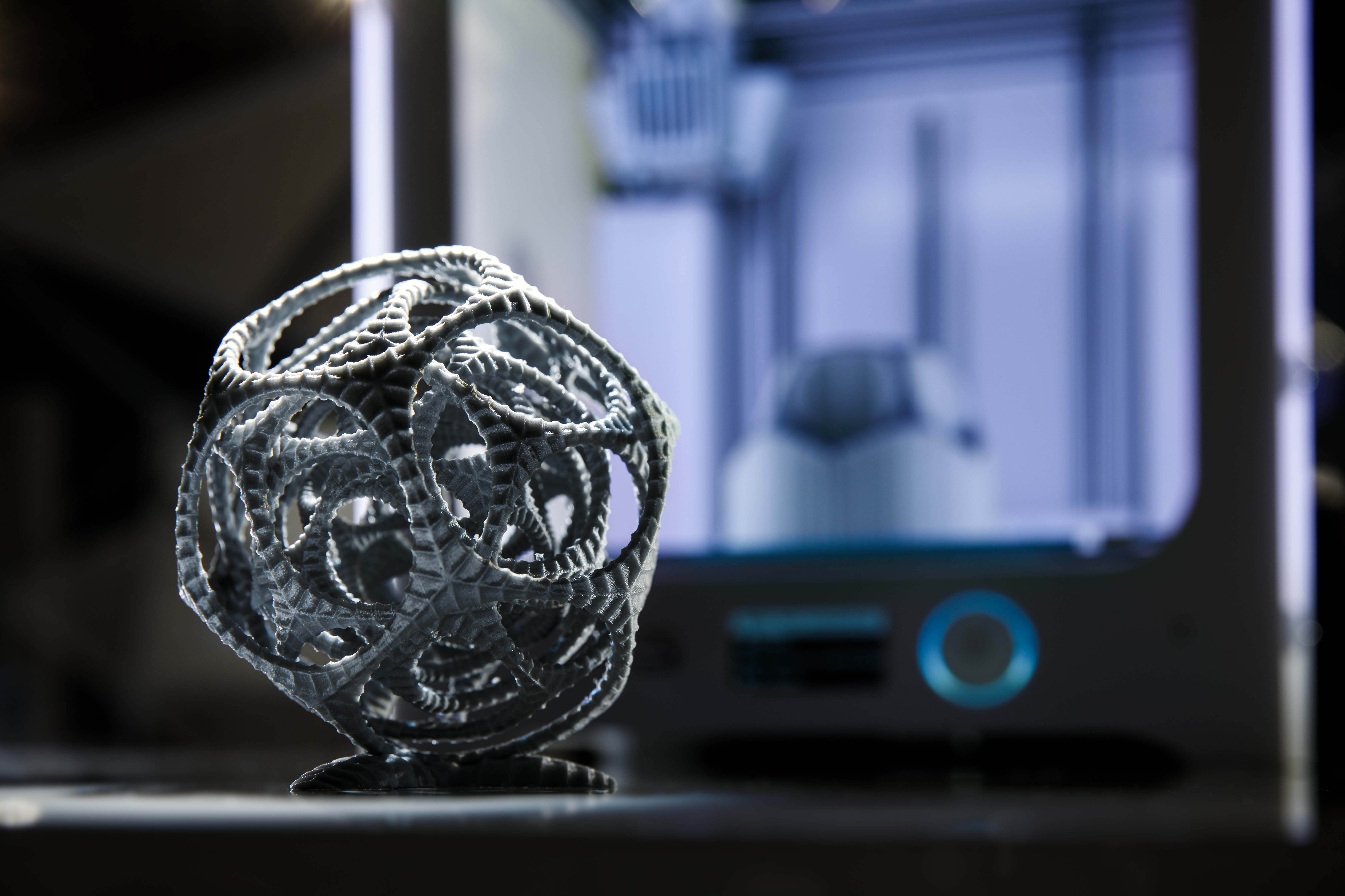
Version 1.0
9,687 downloads
The original dodecahedral kinetic sculpture by Stijn van der Linden a.k.a. Virtox. Made of five nested dodecahedra, each one is limited to rotate around its own axis. It was printed with dual extrusion on an Ultimaker 3 with water-soluble PVA support material.11 points -
Took me forever to do this. And it is still rougher than I would have liked. 3D concept rendering: Finished piece:


 11 points
 -
Here’s my new printer cabinets to keep noise in my office down and to store them in a neat & tidy way. Made by my favorite furniture maker. PSU, cables, Raspberry Pi with OctoPrint are stowed in the drawers underneath the printers. The printers can slide out for filament change or other maintenance. The doors have gaskets so the noise can’t escape.


 11 points
 -
I MADE A BETTER AND INTERACTIVE GRAPHS HERE: http://gr5.org/mat/ Okay well this post will grow when I add temperature properties. I've been thinking about posting this for a few years. Here is a graph showing some mechanical properties of some common filaments. Please read explanation as this is a complicated subject. Click to zoom in on chart (click 3 times - first click zooms, second click jumps to actual image, third click zooms into that). Higher up is stronger. Farther to the right is stiffer (not steel). Both axes are logarithmic. Most data is published by various manufacturers. I have personally verified a few of these numbers with my own equipment. VERTICAL AXIS So the vertical axis is tensile strength. It's measured by pulling on a cylinder of material from each end until it breaks. Divide the force by the cross sectional area and you get the strength in psi (pounds per square inch) or MPa (mega pascals) for those who prefer metric (like me). Anyway this is kind of complicated because the materials towards the left are quite stretchy and long before their breaking point the parts are damaged. The point where it won't bounce back is the yield strength but I choose the ultimate aka breaking strength. Or whichever was higher (some materials actually start to get weaker again - like steel. Or PLA). Now the weakest material shown, PP is actually showing the yield strength - it is actually much stronger than you would think so this is unfair. But the machine that UM used to test PP wasn't long enough to test this value (the part never broke). HORIZONTAL AXIS This is the tensile young's modulus wherever possible (sometimes it's the flexural modulus which is close enough). This is tricky and complicated but for the most part indicates how stretchy/flexible a material is. So ninjaflex on the left edge has very similar flexibility to a rubber band. Most nylons (except shapeways) are much more flexible than PLA or ABS and this makes them very tough. Materials to the upper left will be tough as hell. In fact anything to the left of and including "nylon UM" can probably be driven over by a car and come out just fine afterwards. Or a tank. Or you can throw it against a brick wall with full strength or hit it with a hammer. Most of those materials in most shapes can handle it. Tough. Materials to the lower right are more likely brittle (hence glass is the most brittle). XT is probably somewhat brittle among filaments (I've never tried it). Materials to the right tend to be hard. The hardness scale and the modulus are closely intertwined. Things to the right are harder, to the left are softer. Specific Materials The table that created the graphs here is at the bottom of this post. Red materials above are for comparison and are not filaments. ABS is shown in green above - this shows how different people testing the same material get different results. Most of these tests (maybe all) were done on printed parts which will be a bit down and to the left of injection molded parts. Two different companies tested Taulman Nylon 645. With professional equipment and also got different values hence the two data points. UM=Ultimaker in the chart. XT is colorfabb. POMC is delrin. I'm very skeptical about nylforce CF specs. If someone wants to send me some I'll print and test it with my stress/strain machine. In the graph above there are a few points to keep in mind. Materials with low softening temp are the easiest to print because they don't warp much in the temperature range from this temperature to room temp. It's only about 30C difference. As you move to the right the yellow group of materials is a little harder - parts are more likely to warp off the bed so you need to learn some tricks. Maybe. They really aren't much worse. The orange area with ABS and other materials are tricky now for a few reasons - they don't stick as well to the bed, you are now getting into materials with layer adhesion issues so you need to lower the fans, the bed takes much longer to heat up - you really need to enclose the printer to raise air temp to around 35C to get decent quality. The red group needs nozzles that can go over 300C (no teflon please!) and print beds that can go to 150C and ambient air in the printer at 80C. So this requires special equipment. Also as you move to the right your materials can handle working environments of higher temperature. The green materials can't handle a car with windows rolled up on a hot sunny day (neither can a human for that matter). The yellow materials can handle this but can't handle boiling water. The orange materials can handle boiling water. SOFTENING TEMP (horizontal axis) In the graph above the horizontal axis is a mythical characteristic called "softening temp". For many of these materials in the green and yellow area I have tested them myself personally by sticking them in hot water. Above a certain temp they can be easily bent and when they cool a few degrees they stay in the new shape. That's what I call the softening temp but in reality this value came from HDT (heat deflection temp) or glass temp in other cases or functional temperature in other cases. It's a mixed bag. So it's very approximate! Normally you want the heated bed at a temperature a bit above this temperature such that the material is soft enough to flex a little and spread out the warping forces. PRINTING TEMP (vertical axis) Also somewhat arbitrary as some materials like PLA have a wide range of printing temps. Also variation in heater block design and variations in nozzle length, filament diameter, airflow touching nozzle, and more - affect what this temp should be. But it is a good place to start. Mostly I'm just showing that the red materials need special equipment to print them. The green, yellow, and orange materials can all mostly be printed by most printers no problem. In table below, take all values with a grain of salt. Especially temperatures. For tensile modulus notes read "horizontal axis" paragraph far above. For tensile strength read "vertical axis" far above. For softening temp - please read "softening temp" paragraph above. I've already fixed several mistakes in the table below but ONLY on the website - please go my website for better data! gr5 materials
 11 points
 -
My name is Ruben, I'm a 26 year old software developer working at Cura. I've been at Ultimaker for 3 years. My day-to-day task consists of processing bug reports, fixing bugs and developing new features for Cura. I like to think of myself as the one guy that knows about all components of Cura: Front-end, back-end, translations, profiles, etc. Basically being very broad. Nowadays I'm not the only one any more that knows both front-end and back-end, but I'm still quite knowledgable about Cura and the go-to guy for a lot of colleagues. I'm quite an idealist when it comes to open source software, and a champion of keeping Cura open. So I'm doing the best I can to keep the process open, keep Cura usable for the whole of the 3D printing community, and involve the community. The other influence I try to exert on Cura is to make it more stable (as opposed to featuritis) through automating tests and taking care of bug fixes. Aside from work I like to play bass guitar, write subtitles for films and of course to program. I'm afraid no music of mine has been published on the internet, but you can see my subtitles online and of course my hobby programming projects, though I'm afraid that I tend to not finish most of those.11 points
-
Hello! Je reviens par ici avec un nouveau montage: Utilisation de PLA avec une buse de 0,4. Le squelette a une envergure de 1m60 ailes déployées. Pour s'imaginer, le crâne du bout du bec au bout de la crête fait 40cm (je l'ai imprimé en 3 parties), ce qui m'a un peu fait suer pour l'assemblage (peur que le poids fasse pencher l'ensemble ). Mais au final ça a été. Je ne saurais pas vraiment dire le temps total d'impression parce que ça fait un petit moment que ça a été fait. Mais bon, le temps de peindre, faire son petit coin photo etc etc....


 11 points
 -
Invested 2 hrs of work and had some fun today. @ultiarjan: couldn't resist11 points
-
Now I can trully say that I have this fully working. It might be summer but Winter is coming. Printed at 65mm/s 0.15 layer with supercheap pla. 4h print. Zero errors. Sliced with Cura. I need to align x/y a bit better but today finally had time to watch it print a long 4h. Totally unattended until the prime tower fells. But even so the print didn't fail. Printed design: https://www.youmagine.com/designs/robot-ice-winter-is-coming

 11 points
 -
I finally had to give up my attempts to reset the password and do as Dim3nsioner :-) I would strongly suggest Ultimaker, as many of the other heavy users here does, to step back a few steps and reopen the old forum. Then you should set up some proper internal meetings, possibly hire an expert to sort out internal conflicts and help focusing Ultimaker on future goals. The person who designed this forum, and the person who took the decision to put it online should be moved to other positions in Ultimaker in my opinion. I can not recall that I have seen anything as badly handled as this in my rather extensive history on various forums the past 15 years. When I recommend people to buy and Ultimaker my two main points are that it is common and that it has a great user community. I do not point at it's great printing quality anymore as the competitors has caught up or are even ahead. I think Ultimaker are not even close to realizing the value of the community and all the information in the old threads and how volatile this might be. Lots of nice and clever people spend an awful lot of time here for free just to help others, which creates a nice experience around Ultimaker. Most 3D-printer manufacturers could only dream of having this kind of community and Ultimaker for sure is playing with fire right now. I am probably moving on if the forum does not get back to something like it was before. There is a demand for good discussion 3d-printing discussion boards and I am sure someone will step in unless Ultimaker does something drastic. So please Ultimaker, step back a few steps, get back the old forum, take your time sorting out internal conflicts and strategy, then take your summer vacation and postpone any updated forums until autumn!11 points
-
And so it starts. Just go an email from high up asking me not to reply on the forum anymore. I'm not backing down. I think you guys are too important for this. I'll keep you updated.11 points


This leaderboard is set to Amsterdam/GMT+02:00