


dbotos
-
Posts
58 -
Joined
-
Last visited
Content Type
Forums
Events
3D Prints
Everything posted by dbotos
-

temperature sensor setting for Ultimaker Original heated bed upgrade?
dbotos replied to dbotos's topic in UltiMaker Cura
Standalone PID with DC output SSR is alive and working! US Ultimaker support sent a new main electronics board (version 1.5.7), which I installed and tested before hooking up the standalone PID. Didn't help - the little heated bed board has a mind of it's own and keeps the heated bed on constantly.

-
temperature sensor setting for Ultimaker Original heated bed upgrade?
dbotos replied to dbotos's topic in UltiMaker Cura
Oops - SSR is an AC-output model. Got a DC-output one on order. Heard back from US Ultimaker support today. They're going to send another board and a J4 cable. I'm not holding my breath waiting for amazement, but I'll try it when it arrives. -
temperature sensor setting for Ultimaker Original heated bed upgrade?
dbotos replied to dbotos's topic in UltiMaker Cura
No reply from US Ultimaker support today regarding the second bad heater board, so I went high-tech redneck on the heated bed controls tonight. I had an $18 Sommy PID laying around for another project (that I haven't gotten to yet) and decided to press it into service for the heated bed. I built a control setup for it on a foot-long length of pallet slat. Since the heater runs on 24V, I figured I might as well use the nice Mean Well power supply that came with the heated bed upgrade kit. That meant excising the mating connector from the original failed heater board with a ball burr in the Dremel. Five case pins and four +/- pins and they were all the blade style. The connector has a snout on it, so I made the right size hole in a piece of birch plywood and bent a bracket out of pipe hanger strap to keep it from turning or getting pushed out of the hole. Wires are just soldered to the +/- pins on the bottom. I also desoldered the PT100 connector and put some leads on that going to the PID input terminals. Got the PID options set in the menu and then checked output. Looks like the first SSR I picked out of my bag of 10-amp salvaged ones is a dud. Will have to try another one. Also need to form a cover out of plexiglass for the SSR to make sure I don't accidentally put my body or something else across the terminals.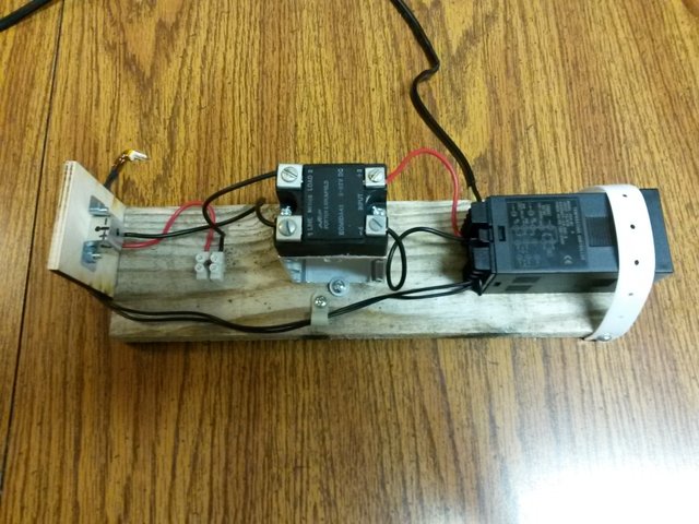

-
temperature sensor setting for Ultimaker Original heated bed upgrade?
dbotos replied to dbotos's topic in UltiMaker Cura
With just the Ultimaker sitting on the table (no USB cable plugged in, just power supply), the D1 LED on the heater board comes on immediately upon plugging in the power supply and stays on regardless of the position of the power switch on the Ultimaker. The main board heated bed output terminals that lead to J4 on the heater board show no voltage. So, not surprising that disconnecting the cable at J4 did nothing either. Something is smelling too, but I don't see anything burnt. Wondering if there's a bad batch of heater boards out there or if it's something else. -
temperature sensor setting for Ultimaker Original heated bed upgrade?
dbotos replied to dbotos's topic in UltiMaker Cura
Got the new heater board today. Installed it, started a print, and the red LED on the heater board never shut off above 70 °C (I let it go up to 90 °C before stopping the print). No toasted MOSFET on the heater board this time. I'm wondering if the Q1 MOSFET on the main board is stuck...
-
temperature sensor setting for Ultimaker Original heated bed upgrade?
dbotos replied to dbotos's topic in UltiMaker Cura
Found the source of the smell. Toasted Q2 MOSFET on the heater board (v1.1): I contacted the vendor I got the heated bed kit from to get a replacement board.
-
temperature sensor setting for Ultimaker Original heated bed upgrade?
dbotos replied to dbotos's topic in UltiMaker Cura
Here is the error log: Recv: echo: M204 P3000.00 R3000.00 T3000.00Recv: echo:Advanced variables: S=Min feedrate (mm/s), T=Min travel feedrate (mm/s), B=minimum segment time (ms), X=maximum XY jerk (mm/s), Z=maximum Z jerk (mm/s), E=maximum E jerk (mm/s)Recv: echo: M205 S0.00 T0.00 B20000 X20.00 Z0.40 E5.00Recv: echo:Home offset (mm):Recv: echo: M206 X0.00 Y0.00 Z0.00Recv: echo:PID settings:Recv: echo: M301 P22.20 I1.08 D114.00 C100.00 L20Recv: echo:Filament settings: DisabledRecv: echo: M200 D3.00Recv: echo: M200 D0Send: M105Recv: ok T:25.4 /0.0 B:33.7 /0.0 B@:0 @:0 ADC B:33.7C->256 T0:25.4C->52Changing monitoring state from 'Connecting' to 'Operational'Send: M105 T0Recv: ok T:25.4 /0.0 B:34.4 /0.0 B@:0 @:0 ADC B:34.4C->257 T0:25.4C->52Changing monitoring state from 'Operational' to 'Printing'Send: N0M110*3Send: N1M92 E100.000000*67Send: N2M190 S70.000000*83Recv: okSend: N2M190 S70.000000*83Recv: okSend: N3M109 S210.000000*102Send: N4G21*62Serial timeout while writing to serial port, trying again.Serial timeout while writing to serial port, trying again.Unexpected error while writing serial port: SerialTimeoutException: 'Write timeout' @ machineCom.py:_sendCommand:565Unexpected error while writing serial port: SerialTimeoutException: 'Write timeout' @ machineCom.py:_sendCommand:565Changing monitoring state from 'Printing' to 'Error: SerialTimeoutException: 'Write time...'Connection closed, closing down monitor -
temperature sensor setting for Ultimaker Original heated bed upgrade?
dbotos replied to dbotos's topic in UltiMaker Cura
1) D1 LED on the little board stayed on constantly. Displayed bed temperature ramped steadily up to 97 °C before I shut things off, despite a 70 °C setpoint. I verified bed temperature with my IR thermometer (measured both sides of the bed, emissivity setting of 0.95), so it looks like the PT100 sensor and its wiring is good. 2) When I had one side of the Ultimaker propped up slightly to observe the D1 LED, I noticed the smell I had smelled last time (silicon / circuit-board like) was coming from underneath the machine and was not something burning off the bed as I had initially assumed. I wonder if something in the circuitry got toasted now that the bed is actually kicking on. 3) When I go to print now, I get a serial timeout exception error. Apparently, problems like to come in threes... :( -
temperature sensor setting for Ultimaker Original heated bed upgrade?
dbotos replied to dbotos's topic in UltiMaker Cura
I found a post where someone had almost the same problem (nearly identical setpoint and too-hot steady state bed temp). Unfortunately, no replies to that post... https://ultimaker.com/en/community/18127-heat-bed-too-hot -
temperature sensor setting for Ultimaker Original heated bed upgrade?
dbotos replied to dbotos's topic in UltiMaker Cura
Yup, the bed got hot. Could feel and smell it. I'll have to run it again and see what the "bed on" LED (D1) on the little board does when it gets above 70 °C: I don't remember the temperature jumping up at all. It just kept climbing and I was sitting there waiting for it to stop its overshoot.

-
temperature sensor setting for Ultimaker Original heated bed upgrade?
dbotos replied to dbotos's topic in UltiMaker Cura
I believe it's measuring fine. I've confirmed proper sensor resistance at ambient where the cable plugs into the little board. If it had excess resistance due to a poor connection that would show up at all temperatures. I can check it at hot to get another data point. It seems like a control problem since I told it 70 and it proceeds to go to what it thinks is 88 and stay there. I'm assuming it would have gotten even hotter if something in the circuitry was stuck "ON". I saw there was an option for PID control of the bed heater in the firmware - I wonder if that might do better if I enabled it. Anyone know good starting values for the PID constants? -
temperature sensor setting for Ultimaker Original heated bed upgrade?
dbotos replied to dbotos's topic in UltiMaker Cura
Good news: the new 2560's AREF measured 5.05 V and once I got it installed, it reported ambient temperature of the hot end and bed correctly (low 20s °C). Bad news: when I went to print, the bed temperature went up to 88 °C and did not come down during printing, despite being set for 70 °C. :angry: -
temperature sensor setting for Ultimaker Original heated bed upgrade?
dbotos replied to dbotos's topic in UltiMaker Cura
Hopefully the whole machine will work better when I get the new 2560 installed with correct analog reference voltage. Stay tuned... I checked that Uno I had and its AREF was a smidge over 5 V. -
temperature sensor setting for Ultimaker Original heated bed upgrade?
dbotos replied to dbotos's topic in UltiMaker Cura
gr5 - I think you just hit the nail on the head. I pulled the 2560 out of the Ultimaker this morning during breakfast (not as bad as I thought - didn't have to unplug all the cables from the main board) and fed it various multiples of battery voltage at lunch just now. It thought 1.68 V was 1.93 V and 3.38 V was 3.87 V. I saw your post and checked the AREF pin with a multimeter: 4.35 V. So instead of 1023/5, it's multiplying by 1023/4.35 to get the digital values (which inflates them by about 15%). If you look back at my results at the bottom of page 2 of this thread, it makes perfect sense: 337 (should-be digital value) x 1.15 ≈ 388 (got 389) 681 (should-be digital value) x 1.15 ≈ 783 (got 781) I looked at the Arduino page about analog reference ( https://www.arduino.cc/en/Reference/AnalogReference ) and it looks like it's supposed to default to 5 V on the 2560. I tried adding a line to my sketch to explicity tell it to do that, but it stayed at 4.35 V. There's also an option to use an external reference (not sure if the combo of main board circuitry and firmware is employing this or not). So, my hot end temperature readings are probably off too, but perhaps not by the same magnitude since it's a different type of sensor and the ratio of analog voltage difference to temperature difference is different. -
temperature sensor setting for Ultimaker Original heated bed upgrade?
dbotos replied to dbotos's topic in UltiMaker Cura
I ordered a new 2560. We'll see if that helps. I've been messing with this for too long not to try that for as cheap as it is. -
temperature sensor setting for Ultimaker Original heated bed upgrade?
dbotos replied to dbotos's topic in UltiMaker Cura
I set the Uno up as a spy (reading the TEMP 3 cable voltage, but not interrupting it). I made a little sketch that read the digital value and also did the math to convert back to analog (repeating once every second). At ambient, the Uno said 1.18 V / 242 (which is close to 20 °C in the table). -
temperature sensor setting for Ultimaker Original heated bed upgrade?
dbotos replied to dbotos's topic in UltiMaker Cura
I fed the Arduino 2560 with different voltages. I bumped BED_MAXTEMP up to 1500 in the firmware so it wouldn't complain. Also added another row to the bottom of the sensor 20 temperature table (1200 °C / 1017). Here are the results: 0 V: Error: MINTEMP triggered, system stopped! (had ground and sensor voltage pins shorted) 1.65 V: 195 °C / 389 (should be more like 130 °C / 337 based on closest row) 3.30 V: 760.7 °C / 781 (should be more like 600 ° / 681 based on closest row) 4.95 V: 1200 °C / 1023 (looks like it maxed out; probably not a reliable data point) So, at ambient, it reads ~50°C higher than it should, at a voltage equivalent to ~130°C it's reading ~65°C higher, and at a voltage equivalent to ~600°C it's reading ~161°C higher. Apparently not an offset problem... -
temperature sensor setting for Ultimaker Original heated bed upgrade?
dbotos replied to dbotos's topic in UltiMaker Cura
Torgeir - all the stuff with the PT100 sensor should happen on the add-on board with the INA826 amplifier. The output of that gets fed right to the ADC and should just be a straight A-D conversion and table lookup. I guess I should ask the Marlin folks if it is in fact a straight conversion without any gain or offset. gr5 - I think I have a two-pronged plan for testing hardware. First, I can take the bed temperature cable that comes out of the add-on board and rout it to an Arduino Uno that I have. A simple sketch with the AnalogRead function can get me the raw ADC value of that voltage. Kind of a "second opinion" from a different Arduino doctor. The other part of the plan would be to apply different voltages to the TEMP 3 input on the main board (where the bed temperature cable normally plugs in) to check the response of the Arduino 2560's ADC. I was thinking 0, 1.5, 3, and 4.5 V (since they're multiples of common battery voltage). For the zero, I'd tie the pin back to ground so it doesn't float. ADC values would be checked via M105 command through the firmware. -
temperature sensor setting for Ultimaker Original heated bed upgrade?
dbotos replied to dbotos's topic in UltiMaker Cura
Here's the issue I opened on the Marlin github page: https://github.com/MarlinFirmware/Marlin/issues/4072 Hopefully the Marlin folks can provide some good guidance. I'll post back here if I get any helpful information over there. -
temperature sensor setting for Ultimaker Original heated bed upgrade?
dbotos replied to dbotos's topic in UltiMaker Cura
Torgeir - I've tried the default firmware with the same results as the custom firmware - it thinks the bed is somewhere slightly above 70 °C when it is physically just above 20 °C. If I do a default firmware load from Cura, it says it loaded "MarlinUltimaker-HBK-250000" at the end. At this point, I've verified that the PT100 sensor's resistance at room temperature and the voltage output from the INA826 circuit are correct for that resistance all the way up to the ADC. So it's something to do with the ADC, which could be either hardware or firmware related. As a quick test this morning, I thought I'd see if I could change the bed temperature since I've been doing all ambient data points. I placed an reusable ice pack in the center of the bed, let it sit for a while, and then used the M105 command to check the temperature. First check said 63.7 °C. Waited a little bit and second check said 62.5 °C. Another wait and third check said 61.6 °C. So, it's responding in the right direction, but it still has what appears to be an offset error in converting the analog voltage to temperature. -
temperature sensor setting for Ultimaker Original heated bed upgrade?
dbotos replied to dbotos's topic in UltiMaker Cura
Torgeir - motherboard 72 is for Ultimaker main board 2.x. I've got a 1.5.6 main board, which should fall under motherboard 7. There's also a motherboard 71, which is really old Ultimaker original (pre 1.5.4 - I think I read somewhere that these were never shipped). I'll have to see if anyone over on the Marlin github page has any suggestions. gr5 - just measured the following voltages where the bed temp cable connector is soldered into the main board: black (Vcc) to blue (GND) = 4.99 / 5.00 VDC red (Vout) to blue (GND) = 1.22 VDC -
temperature sensor setting for Ultimaker Original heated bed upgrade?
dbotos replied to dbotos's topic in UltiMaker Cura
No love. I swapped the cables and pin assignments and it says the bed is 71 °C. Even tried taking the .hex firmware file output by the Arduino software and uploading from within Cura. I'm doubtful that two channels on the ADC are messed up... -
temperature sensor setting for Ultimaker Original heated bed upgrade?
dbotos replied to dbotos's topic in UltiMaker Cura
gr5 - I may have to resort to that. But I have one more thing to try... I uncommented that line in Configuration_adv.h and at room temperature, it returned a bed temperature of 72 °C and an ADC value of 289. This falls in between the table values of 70 °C = 287 and 80 °C = 295. I'm assuming this means that channel of the ADC is messed up. So here's that one more thing to try: In the 1.5.6 Ultimaker main board schematic, there is an unused TEMP 2 channel (for a second hot end). It is identical to the TEMP 3 channel (including the fact that there is no 4.7 kΩ resistor loaded). So, I'm going to try physically swapping the cables plugged into TEMP 2 and TEMP 3 and then swapping the pin assignments in pins.h (in the section that starts with "#if MB(ULTIMAKER)"): currently: #define TEMP_0_PIN 8 #define TEMP_1_PIN 9 #define TEMP_BED_PIN 10 will change to: #define TEMP_0_PIN 8 #define TEMP_1_PIN 10 #define TEMP_BED_PIN 9 -
temperature sensor setting for Ultimaker Original heated bed upgrade?
dbotos replied to dbotos's topic in UltiMaker Cura
I was able to compile and upload custom Marlin firmware from the Arduino software. I made the following changes to Configuration.h: --------------------------------------- 1) replace #ifndef MOTHERBOARD #define MOTHERBOARD BOARD_ULTIMAKER #endif with #define MOTHERBOARD 7 --------------------------------------- 2) replace #define TEMP_SENSOR_BED 0 with #define TEMP_SENSOR_BED 20 --------------------------------------- 3) replace #define INVERT_E0_DIR false with #define INVERT_E0_DIR true --------------------------------------- 4) replace #define DEFAULT_AXIS_STEPS_PER_UNIT {78.7402,78.7402,200.0*8/3,760*1.1} with #define DEFAULT_AXIS_STEPS_PER_UNIT {78.7402,78.7402,200.0*8/3,100} --------------------------------------- 5) replace #define DEFAULT_MAX_ACCELERATION {9000,9000,100,10000} with #define DEFAULT_MAX_ACCELERATION {9000,9000,200,10000} --------------------------------------- I also fixed the first two lines of thermistortables.h for sensor ID 20 (the PT100) before compiling and uploading. Fired up Cura, told it to print something, and it said the bed was 68 °C when it was at room temperature. :( I need to compile again, with the following line uncommented in Configuration_adv.h: #define SHOW_TEMP_ADC_VALUES This is supposed to return the ADC value(s) when you issue an M105 command (along with the temperature info that in normally returns). Hopefully this will give me the information I need to decide whether it's a software or hardware problem... -
temperature sensor setting for Ultimaker Original heated bed upgrade?
dbotos replied to dbotos's topic in UltiMaker Cura
It'd be simple to make the table extend into the sub-zero °C range. I don't plan on personally using my Ultimaker in those kinds of temperatures. If you wanted to code in some minimum temperature limit, it'd probably be a simple matter. No reason why the heater shouldn't work at temperatures that low. Slope of 1023/5 is correct for going from analog to digital. Linear slope dy/dx = (1023-0)/(5-0) = 1023/5. No offset since (0,0) is a point on the function. Yup, I think I've narrowed it down to either the firmware or the ADC. I need to try compiling my own firmware now that I know what settings I need to change for my setup.


