


jonnybischof
-
Posts
1,217 -
Joined
-
Last visited
-
Days Won
1
Content Type
Forums
Events
3D Prints
Posts posted by jonnybischof
-
-
I have never printed Nylon myself, so I can't speak out of any personal experience but just repeat what I read online:
E3D-online had a printing plate specifically for printing Nylon. I bought one some time ago (but never used it to date o.O) and just wanted to look it up, but it's gone from their shop...
The material is called "Garolite", "Tufnol" or "Bakelite" (different brand names I believe).
You could use that instead of the UM2's glass printing plate, or mount it on an Ultimaker Original with some (large) foldback clips.
I read other reports saying that using rafts helps a lot, too. This doesn't solve the problem of Nylon not sticking to your printing plate, but rather works around it by reducing / changing the contact area of your printed parts to the plate.
/edit:
http://www.taulman3d.com/best-print-settings.html
http://richrap.blogspot.co.uk/2013/04/3d-printing-with-nylon-618-filament-in.html
-
Picking up an idea from here:
...Especially the stallGuard2 function - which offers new ways for sensorless homing...
If you didn't follow the linked discussion:
The Trinamic TMC2130 stepper motor driver has a feature called StallGuard2 which detects when the motor stalls, and reports that to the controller.
For now, these drivers aren't available as a ready kit for 3D printers (Note, the Silent StepSticks use the TMC2100 which doesn't have the SG2 feature), and there is no firmware support for the feature.
But that could both be arranged, if there is any actual use for it.
------------------------------------------
Let's say our motor drivers were able to detect and report stalled motors.
Could - and should - this feature be used to simplify the homing process on a 3D printer?
Meaning: Instead of using a limit switch as an endstop, just let the gantry bump into a defined obstacle and have the motor driver report the stall.
--> Any negative effects on the...
motors?
drivers?
gantry mechanics?
homing precision?
...?
------------------------------------------
Motors:
Stalling a stepper motor doesn't have a negative effect on the motor itself. At least not if it's only for a short time.
Drivers:
The Trinamic drivers with SG2 functionality don't have a problem with stalled motors. The feature wouldn't make much sense otherwise...
Gantry mechanics:
A hard "crash" should be avoided. Maybe rubber bumpers can be used?
Homing precision:
There is actually no need for super-precise XY homing, because the position of the printed object on the build plate doesn't need to be accurate or repeatable to 0.001mm. 0.5 to 1mm repeatability would be enough.
The Z axis is another matter entirely, as it does in fact need very precise and repeatable homing.
A hard and precise bumper would be necessary. I doubt that the Ultimaker's leadscrew mechanics will give a precise result, even if there is a hard endstop. Any torsion in the coupling (for those who use a flexible shaft coupling - no go) or maybe even in the leadscrew itself would have a negative impact on precision / repeatability.
Another thing: Homing could sound a little ugly. Wouldn't be a real concern, but if people think there's something wrong, it might be a problem...
------------------------------------------
Why bother at all?
Why not use a driver's feature if it's readily available? It's useful for detecting stalled motors, for example due to things like people's hands obstructing the gantry.
The material savings aren't great, but you can actually save some material costs.
More importantly though, you can save some wiring inside the printer, facilitating the machine's design and shortening assembly time. Now that is a reason to bother!
-
 1
1
-
-
The GCode file contains layer information. Marlin would "simply" need to read through the full gcode file before starting the print, in order to find the amount of layers.
Then, it would have to read the "layer: xx" information instead of just skipping it (because it's a comment line).
It's not as easy as in "you can write that code in 5 minutes" (programming always takes it's time..), but should be doable without problems.
-
Seriously, fix the problems when writing long posts!
Current FF on Win7pro 64bit.
As soon as a reply has a certain amount of lines, it scrolls up everytime you hit a key, away from the reply box. This means you have to write blid, or use an external editor to write posts.
I have to cut & paste my texts into notepad in order to be able to write anything. When I want to insert a picture or link, I need to cut & paste into the form, add the link, then cut & paste back into notepad. This sucks big time!
There is no way I'll be here long if these issues aren't fixed.
/edit:
Also, as soon as a reply becomes too long, I have to click the "post comment" button twice in order to save the post. This is a bit unsettling because there is no way to delete accidental double posts...
-
Hi jonnybischof,
Thank you for your very detailed infomation :c)
...
Ian.
You're welcome

I can't reproduce your 1.55W, though...
You're using:
19.5 V UMO power supply
12 V, 0.15 A fan
90 Ohms resistor
right?
So, the "equivalent resistor" for your fan is 12V / 0.15 A = 80 Ohms.
Total resistance: 80 + 90 = 170 Ohms
19.5 V / 170 Ohms = 0.115 A effective current.
Resistor's portion:
90 Ohms * 0.115 A = 10.3 V
10.3 V * 0.115 A = 1.19 W
Fan's portion:
80 Ohms * 0.115 A = 9.2 V
a) Your fan is underpowered in this situation. It might suffice to cool the E3D, but it's not an ideal solution
b) 1.2W is definitely too much load for a 0.6W rated resistor. It will get very hot, possibly up to the point where the soldering tin might melt.
Power ratings should never be exceeded, unless you know exactly what you're doing.
The correct resistor for your fan would be:
(19.5 V - 12 V) / 0.15 A = 50 Ohms (nearest E24 value: 51 Ohms)
7.5 V * 0.15 A = 1.125 W --> Next standard power rating: 2 W
So, you should get a 51 Ohms, 2 W resistor (5% or better tolerance).
The resistor will get quite hot still, so as I mentioned before, the resistor solution is not too nice for fans above ~ 70 mA. A power converter (DC/DC) is preferrable here.
-------------------------------
Wiring:
...
Also as far as I can see, the only way to power the fan is to de-solder the power socket from the UM board and wire the fan in series, does anyone know of a better way to do this?
Many thanks and kind regards.
Ian.
(It seems to be impossible to quote your first post, this forum is plain awful -.-)
I overread this the first time, but now it struck me that there's a serious error in the instructions Joshua gave you. He told you to wire the fan in series to the power input, but he meant to say that you need to wire the resistor in series to the fan, and put that assembly directly on the UMO power supply input.
So, please do not desolder your power socket!
I made a sketch for the correct wiring:

I'd recommend you use the marked points for soldering. They are large and well accessible.
-
I'd just use the resistor - for a small fan (12V, less than 70 mA or 0.84W) this is no problem, and you don't lose much energy.
If you have a larger fan with more than 1W power rating, then you should either take a fat (1W+) resistor, or use a DC/DC voltage converter.
Example for small fan:
12 V fan, 40 mA (0.5W power rating)
Input voltage: 19.5 V (UMO power supply)
So, you want the resistor to take away 19.5 - 12 = 7.5 V from the fan, at 40 mA.
That means you need a 7.5 V / 40 mA = 187.5 Ohms resistor.
Nearest Preferred E-series value: 180 Ohms.
Resistor's power rating: 7.5 V * 40 mA = 0.3 W (use a 0.5W resistor)
Of course you need to adjust the values for your particular fan.
You can also turn the calculation around and see what happens if you take "any" resistor value:
Same example fan as before:
12 V fan, 40 mA (0.5W power rating)
Let's say the fan were a resistor (approximation), then it's value would be:
12 V / 40 mA = 300 Ohms
Now, we put your 90 Ohms resistor in series to that 300 Ohms fan, which means we have a total resistance of 390 Ohms.
Powering this from the UMO power supply, we get:
19.5 V / 390 Ohms = 50 mA
The fan's portion of this would be:
300 Ohms * 50 mA = 15 V
and the resistor's portion:
90 Ohms * 50 mA = 4.5 V
Now, back to the power ratings:
Fan: 15 V * 50 mA = 0.75 W
Resistor: 4.5 V * 50 mA = 0.225 W (still recommend a 0.5W resistor)
Our example fan should be able to take that overload without any problems, as long as it doesn't exceed any mechanical rpm limits. (Read: You shouldn't overdrive fans that already run at very high speeds above 10k rpm).
/edit:
About wasting energy: In the first example, we had 0.3W power on our resistor. This energy is wasted (turned into heat). But it's not much. If you use a DC/DC converter instead, you get around 85% efficiency, meaning the converter would waste around 0.075W for a 0.5W fan. This is less (meaning more efficient) than using a resistor, but we're talking about very small amounts of energy which can be neglected.
Hence: Prefer the simpler solution. Note that using a DC/DC converter can be simpler than using a resistor, because you just have to hook it up, no calculations whatsoever.
-
Looks great indeed!
How did you align the aluminum extrusions? I've put together a similar frame myself, but had a lot of trouble getting "almost" perfect 90° angles everywhere...
Is the frame rigid? The pieces you used to hold the extrusions together seem very small (side-note: I like my overkill-tank-like-stainless-steel-constructions).
-
That's why I'm going for the TMC260, which has SG2, too. StealthChop is useless for 3D printers.
dcStep seems interesting, though. The IC package is also very interesting (low-resistance QFN with large exposed die pad instead of qfp with only the "legs" as electrical contacts).
Well, I'm still in the design phase for my next project, maybe I'll actually switch drivers

The TMC2130 is not suitable for a Marlin platform, though. There's no headroom for integrating it's advanced features..
/edit:
The new TMC2130 costs almost double as much as the TMC2100... Not much of a difference to the TMC260, though.
-
The problem with mechanical limit switches is, you can't travel beyond the switches anyways - you'd run into the switch.
-
Afaik the UM2 avoids this problem by lowering the platform all the way down once the print is finished.
I don't have one myself, but I remember seeing this in videos.
I suppose this is part of the "End-GCode" for the Ultimaker 2 Cura profile.
-
jonnybischof: Do you also use digital current control(page 24 in the datasheet) like the UM2 or only the POT for setting the current? ...
I'm using only the analog current control (mechanical potentiometer). I just didn't want to bother implementing a digital potentiometer, because these potentiometers aren't linear and the output voltage would need to be checked (by feeding it back to the Arduino's ADC). Most of all, I don't want to have to start tinkering with Marlin because I'll soon start working on a successor to the Marlin firmware / Arduino platform.
...And do you thing that the INDEX pin (pin 21, page 33 in the datasheet) could be used to detect skipped step? ...If I understand that function correctly, the Index signal is only an output from the indexer circuit for the user to be able to track its position. I don't think that a motor skipping steps has any impact on the Index signal, because the indexer doesn't have a feedback circuit.
But I didn't actually verify that - I'll ask the Trinamic support about it. They're very helpful
...And do you have heatsinks on the chips?The heatsinks are integrated into the PCB. It's the nice and blingy golden "wings" on the sides of the driver ;)I hope they will suffice and that no more heatsinking will be necessary.
My plan is to have the prototype running by the weekend, and analyze the driver's temperatures with an infrared camera. Stay tuned for results!
The Silent StepSticks have a very small PCB, which is why they will always need heatsinking and / or forced air cooling. I'm hoping to do away with that.
Small update: I found out why my temperature sensors didn't work. Connected them to 5V instead of GND *d'oh*
/edit:
I'll take some measurements before bothering the Trinamic support. I don't understand the driver well enough just yet...
-
PLEEEEAASE do away with the square and oddly colored smileys. They's fugly :(
I want my classic smileys back ;(
-
1
-
-
A little update from my side:
Been very busy putting my own TMC2100 Marlin platform together the last few days. I didn't have much time to test it yet, but I seem to have a few problems for now.
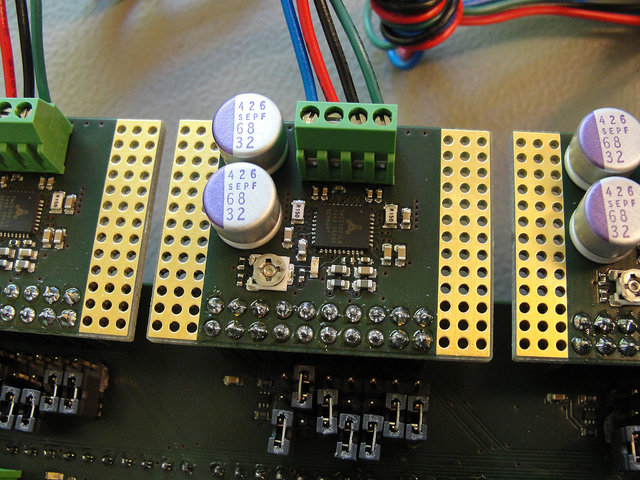
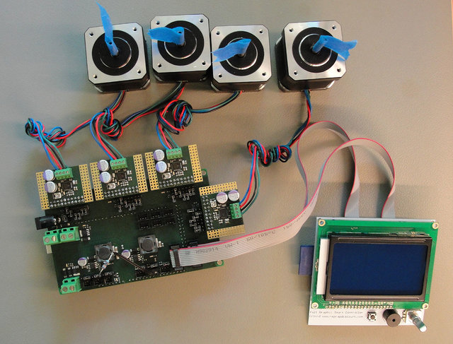
As you can see, my prototype gives me full access to all 7 CFG pins, with the possibility to tie them high, low or leave them floating. It will probably turn out that most of these settings are unnecessary, but that's what I want to find out with the prototype..
While I can get my motors to turn, they whine a lot as soon as they're not moving anymore, and the drivers get quite hot (around 60°C maybe? Didn't leave them like that for long, I'm not using any kind of forced cooling).
Also, the temperature sensors don't work yet so I couldn't start an actual print. But I'll be fixing these things in the next few days, so stay tuned
/edit:
I know there's some things that aren't very good on my quickly put together test setup. The motors have no load, and the cables are long and not twisted. I hope that is the problem why they whine. But as I said, more news later

-
You (Team Ultimaker, @SandervG) should get in touch with @foehnsturm about that dual extrusion problem.
He's shown a brilliant solution using a toolhead interchange system instead of making an actual dual-extruder hotend.
Users can print the essential parts themselves, but you could offer a kit for the hotend, hardware and stuff that is needed. And integration into Cura would be very sweet
-
1
-
-
Ok, that sounds like the Ulticontroller is actually faulty. If the printer can print fine via USB connection, then I suppose you contact Ultimaker support and ask for a replacement. Add a link to this topic in the ticket to speed things up a bit.
-
1
-
-
-- deleted --
Not used to the new forum yet o.O
-
I suppose you're talking about an UM-Original, not a UM2?
In your video, the display fails after you started heating the extruder.
Does the display also fail if you don't start heating the extruder? (For example, just browse through some menus for some time, but don't start heating up)
Maybe the display fails when you push the button a little harder than necessary? (could be a slack joint)
When you disconnect the UltiController, can you print via USB connection without any problems?
When you installed the new (default) firmware from Cura, did you use the "Ultimaker Original" (not "Ultimaker Original +") machine profile in Cura?
Afaik, you don't need to change the firmware when you add an Ulticontroller to your UMO, because it's enabled in the default firmware anyways.
-
Hi @lars86, I had to make several changes to the one I last showed in this topic. Using multiple linear bearings in a row turned out to be a bad idea - very difficult to get them aligned properly.
This is why I switched to Misumi's LHSSL12 linear bearing with pillow block.
I think there is a newer sketch in my Ultimaker Black Edition thread showing this solution, which works pretty well so far. The metal construction is very stiff and moves well along the z-axis. I'm not 100% happy with how the leadscrew is mounted, but I guess it works alright..
-
1
-
-
...Man sollte halt die Windows Updates um 3 Uhr früh vermeiden
Und da hapert es schon bei vielen Normalsterblichen
-
Anyone knows if something like this could work connecting this between the crossflow fan and the board direct 24v output to the fan? http://www.aliexpress.com/item/6V-30V-6A-Reversible-DC-Motor-Speed-Control-PWM-Controller-Switch-PWM-Regulation-Fan-Control-for/32221565091.html
It could work - as long as you don't put the control switch to reverse mode. That will probably damage the fan. And you can't control it through the UMO fan output anymore because most control inputs of such drivers won't allow 19V input.
-
This fan still draws around 10 times as much current as a usual fan - That means much higher inductive load and higher voltage spikes on PWM control. NPN transistor? Not a good idea...
You could try flattening out that PWM by adding an RC lowpass filter / tank after the PWM output stage. It might take some tinkering with different values, but it's possible to come pretty close to a regulated DC voltage with that trick.
I'll try it out myself once I get to install my crossflow fan. But there's too much other stuff to tend to atm :(
-
...
No bowden?
...
In the spirit of the Ultimaker concept: If it doesn't produce a good quality output - don't do it.
Retraction in a Bowden-fed printer is useful to reduce oozing for the short time it takes the printhead to travel to a new position. After that, you have to continue printing or the nozzle will start to ooze.
That is not useful for a dual-extrusion setup imho - because a toolhead might be parked for a long time until it's brought to use. A very good flow control is necessary in order to produce usable results.
I'd even consider making a script that lowers nozzle temperature when toolheads are parked for long times.
(Note: In conjunction with the "minimum layer time" feature, this script can be very simple and still produce usable results).
...
Size matters
...
True as long as you're constrained to an Ultimaker printer. I would choose whether to stay with the UM or make a completely different printer and then optimize the design only for that selected purpose.
If someone else wants to adapt the idea for another printer, he'll have to adapt the design anyways. *Cough* I'm sooooo not designing a printer around the toolhead changing idea right now :cool:.
...
1.75 instead of 3 mm?
...
For me, 1.75mm filament is not an option. But then again, I won't be constrained by the Ultimaker's space budget. My current sketch says I have 248mm of space freely available for toolhead-parking. Thanks to the H-Bot configuration, I can use that whole space instead of just the corners. Also, I can increase any of the dimensions if necessary - it's still a sketch
If I read your post correctly, then this is mostly a "Should I develop my design further to fit into an Ultimaker printer, or go for a new printer entirely?" question.
My thoughts on that:
Making a proof-of-concept inside the Ultimaker is a very good and efficient way to develop this idea. It helps a lot if your design is completely reversible and easily mounted.
Most people (probably everyone that already has an UM) will want an easy upgrade rather than a new printer.
You'll lose valuable print space, but if it's reversible you can still cover most needs.
In order to really profit from this design (have more than two toolheads at the same time), you'll have to use an H-Bot gantry, meaning a dedicated printer design. But how many people will really
wantneed more than two hotends? Probably not that many...And to get the most out of it, you'll not only need a new printer (and electronics with enough motor drivers, cooling fan outputs and so on), but also further development in slicing software, such as the possibility to configure all these toolheads, have different tools use different layer heights and many other things that can be possible.
-
Thanks for that Yellowshark
When I return to school next week, I'll order a 100M of the loose filament from Faberdashery and see how I get on. Can I ask if tangles are a problem with the loose stuff?
These new Ultimaker 2 printers are going down a storm in the classroom and I am just so impressed with what the students are producing. The combination of powerful design software [inventor] and reliable printing is a game changer.
Tangles are actually a problem, depending on how you use the filament. If you use a holder for coiled filament you shouldn't have any problems.
I'm in the process of making a holder specifically aimed at solving these problems once and for all. Might take some more days though as I'm very busy atm...
-
The bottomline is simple - Buy ONLY high quality 3D printing filament! - Sure you can get cheap stuff for half the price. But the trouble is never, ever, ever, ever worth it
All consumer grade 3D printers are made for either 1.75mm or 2.85mm filament (the latter is generally referred to as 3mm). 3.00mm filament doesn't have ANYTHING to do with 3D printers, instead that's what is used in plastic welding. These filaments usually also don't need to be manufactured to a very high diameter tolerance. Because it doesn't matter that much in plastic welding. But it does matter in 3D printing.
Any decent 3D printing filament is made to 2.85mm spec. If not - it's NOT 3D printing filament (even if someone might sell it as 3D printing filament).
/Edit:
I can also highly recommend Faberdashery PLA! Especially if you're in the UK and can save taxes and intl. shipping costs. It's expensive, but one of the best there is.
You'll need to print holders for the coiled filament (comes without spools) - but that's a good way to get rid of the cheap filament laying around


How to power E3D V6 fan?
in Third party products & modifications
Posted · Edited by Guest
You're right about the fan - Calculating the equivalent resistance from the nominal values (12 V, 0.15 A) doesn't give you any precise results.
Well, now that you have the fan running, you can re-calculate the fan's actual equivalent resistance.
We have 19.44 V - 14.5 V = 4.94 V on the resistor. 4.94 V / 50.1 Ohms = 98.6 mA current.
14.5 V / 98.6 mA = 147 Ohms for the fan.
That means the fan actually draws less current than nominal. This is not unusual, simple manufacturing process thingy.
The difference is higher than I'd have anticipated, but then again it's not an expensive, high quality fan...
I don't think it's a problem to run it at 14.5V, other than the fact that it runs noisier this way. The E3D fans aren't exactly quiet, even at 12V.
/edit:
By the way: If you hook up the resistors in parallel, then you divide the power dissipation between them. Two 2W resistors in parallel equal one 4W resistor. You can take two or three resistors with a lower power rating using this trick