


anon4321
-
Posts
914 -
Joined
-
Last visited
-
Days Won
1
Content Type
Forums
Events
3D Prints
Posts posted by anon4321
-
-
Another source: http://www.watterott.com/en/Heatsinks-6-3x8mm
This adhesive works well: http://www.arcticsilver.com/arctic_alumina_thermal_adhesive.htm
-
It's possible that the PWM frequency is too high and your transistor isn't switching on and off fast enough. So the transistor might be operating in the linear region longer then it should and dissipating a lot of power.
-
sorry my reply was a little late. So pin 13 didn't work? strange...
-
I installed Eagle and checked. The LEDs output is just the 19V supply. There is nothing controlling it.
If I were you, I would just duplicate the fan controller portion of the shield. It's a BD679 darlington pair with a 1k current limiting resistor for the base. Good for a couple amps.
Buy a couple extra BD679 in as backups for the one on the shield. Then you have a spare should the fan been shorted.
The marlin firmware seems to define a LED control pin as pin 13. If you figure out what pin that maps to on the shield and use it for the LED drive then I think you will get GCODE control of the LEDs without changing the firmware. Although I'm making a lot of assumptions.
See line 1319 here https://github.com/Ultimaker/Marlin/blob/Marlin_v1/Marlin/pins.h
This is the fan control portion of the shield:
.thumb.png.cd314c84aecc48d1ea600c45c6f61041.png)
Looks like pin 13 is in the group near heated bed output
Good luck.
-
 1
1
-
-
Unfortunately, as near as I can remember, that WIKI is incorrect. I don't believe the LED connector can be PWM'ed. I believe it is hardwired to 19V.
You'll need EagleCAD to open the files but they are here:
https://github.com/Ultimaker/UltimakerOriginal/tree/master/1090_Arduino_Mega_Ultimaker_Shield_1.5.7
If my memory is correct, you might be able to run the LEDs off the second heater output if you don't have a dual extruder output. But you would need LEDs that can run on 19V. And you might need to tweak the firmware.
-
1
-
-
No I would contact UM about the driver and the problem in general. One unfortunate design issue with the shield is that the drivers ARE flipped as you have discovered. And unfortunately, inserting the drivers the wrong way destroys them when the power is applied.
So the overheating of the regulator could be due to the feeder motor driver being damaged.
You can do two things to see if the feeder driver is destroyed:
Without any filament in, does the feeder still feed?
If you remove the feeder driver (the one you flipped around), does the display and other three axes work?
Alternatively, the drivers are relatively cheap, it might be quicker to source them from some place like amazon or ebay. Just search for
a4983 driver
stepstick driver
Just make sure that if you get a replacement from some other place than UM that:
the driver has the header pins soldered on unless you can solder them and
that the little heatsink is supplied and is attached unless you can get thermal adhesive and can attach them yourself.
-
I think there is a bit of confusion here. I believe the OP was asking how to reattach the heatsinks in the stepper DRIVERs not to the stepper motors themselves. I used the Arctic Alumina Thermal Adhesive on the heatsink for the drivers with good results. With such a small contact area, they can be removed with a small wrench and a twisting motion. Then you can scrape the adhesive off and clean with alcohol and reattach.
Note that for the drivers on the UMO, there is no mechanical mechanism to hold the heatsinks on like you would have with a CPU. So a thermal adhesive needs to be used.
In the states, the Arctic Alumina Thermal Adhesive is available at "good" electronics stores that sell computer parts like MicroCenter. Not sure where the OP is located but Amazon would be a good source too. Or a site like Newegg if they ship to the OP's location.
-
This has worked for me for attaching the tiny heatsinks to the stepper drivers. You need like a dot the size of a pin head.
http://www.arcticsilver.com/arctic_alumina_thermal_adhesive.htm
-
Errr carefully check to see if it is hot. Also note that it is cooled by the airflow along with the drivers.
-
Does it print when both USB and power are plugged in and turned on?
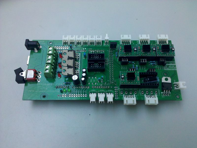
You appear to have a V1,5 board. On that board there is a 12V regulator which powers the mega board. That regulator has thermal protection which may cause it to shutdown or it could be marginal and just shutting down or not regulating well
If it's printing when both are plugged in and on, that regulator is most likely the problem. When the USB is plugged in it is actually plugged into the mega and directly provides 5V to it.
Or there is a problem where that power flows from the regulator to the mega board so check that there are no bent pins and that the jumper that controls if 12V is provided to the maga is well seated. I can 't find the jumper in the pics so it might not be on the later revision. I believe it was labelled ARD_PWR.
Anyway, the IC1 IC is what supplies the 12V to the arduino when running stand alone without the USB plugged in. It's in the lower right in the picture below.
Check to see if it is hot.
-
Hmmm, this seems to be a good starting point... Seems to be using the Kinect 2.
Or better yet:
https://channel9.msdn.com/Blogs/3D-Printing/3D-Builder-Tutorial-Part-5-3D-Scanning-with-Kinect-V2
http://video.ch9.ms/ch9/7543/27d81b6d-0ae2-4431-8016-c49810ae7543/3DBuilderTutorialPart5_high.mp4
-
1
-
-
Oh and a question... Is it hand solder-able or will it need to be reflowed?
-
Hi Jonny, it's been a long time!
This is a very cool idea. Couple comments/suggestions....
- I know you are short on pins but it would be awesome to have the one fan output switchable so if you have something like the E3D type, you can turn off the head fan.
- I was working on a Z probe, this would require two more pins, one for the servo PWM and the other for the probe.
You mentioned Marlin, I would think this could be integrated into it assuming that the I2C pins are available and I2C can run concurrently with Marlin's primary interrupt routine. Two things I'm not sure about!
-
-
-
They met their goal:
-
I didn't notice this when I first converted to the silent drivers.
MS1 on all driver sockets is grounded using a 100K resistor. When there is no jumper installed this pin is GND. When there is a jumper, it is at 5V. This is contrary to the other two, MS2 and MS3. When they don't have a jumper, they are open. With a jumper they are 5V.
So I think it's much simpliler than we have been on about. Solder in the full header and remove all jumpers and stab them in. This should result in CFG1 being grounded and CFG2 being open.
Based on the schematic, CFG3 is not connected unless you bridge the solder pads.
-
Hmmm, very interesting. I checked the Mega's schematic and board files and there is a bridge that can be cut that disconnects the USB GND from the power GND.
This MAY, REPEAT MAY prevent the Mega from running on USB power. CUT THIS AT YOUR OWN RISK.
I think the worse case is that USB comm stops working but you should be able to reverse it with a blob of solder.

-
1
-
-
I think that page is incorrect. As far as I know, USB power goes directly to the Arduino's USB port. If there is a jumper to disconnect it, it would be on the Arduino. As far as I know, there is no such jumper on the Arduino.
-
UMO or UM2? There is no such jumper for the UMO but you can unsolder/solder some things on the Arduino to disconnect the USB power so it doesn't power the electronics when the USB is plugged in.
http://ultimaker.ipbhost.com/uploads/gallery/album_699/gallery_33216_699_3303656.jpg
-
Also, are you sure the heater isn't "full on" indicated by a solid light on the shield. Place the printer on a shiny surface and dim the lights, you should see the LED pulsing if it isn't "full on". If it is "full on" and the temp isn't at the set point, no amount of PID tuning will fix it.
-
Use Marlin's autotune, see my link.
-
The "load" on the hotend impacts the PID loop's ability to maintain the temp as does the hotend design.
http://reprap.org/wiki/PID_Tuning
The other issue might be that the 24V heater may not generate enough heat at 19V for your configuration. You would see this as a solid, always on LED for the heater when the temp drops.
Check all heater connections to make sure you aren't losing power in a bad connection. This will show up as heat in the connection which can destroy the connector or worse....
-
Did you check the fan at the same distance from the bed as the print test?
Is the bed heated?
Did you retune the PID when you switched to the e3d hotend?
Is your E3D heater 12V or 24V?
.png.ee2bd1a7311440ea098298ebb6bc84cf.png)

Printhead controller
in Third party products & modifications
Posted
Hey Jonny! any update on this ?
Do you have a source for a suitable PT1000? I thinking of a similar solution?