


muttstang
-
Posts
51 -
Joined
-
Last visited
Content Type
Forums
Events
3D Prints
Posts posted by muttstang
-
-
So I can bypass it by adding a .2 Z layer overlap. Not sure why this has changed but I don't like it....
-
Here are a few of the projects I've worked on using the Ultimaker 2+
There are 3 select fire blasters, and the pump blaster is a pistol grip conversion.
The OLED mount with rail on the back are printed

The battery cover in the front grip is a printed part along with some internal pieces

Stock extension and top rail are printed

Masterkey is printed

Stock extension and handle fill with knobs are printed

Pump grip and main grip along with trigger are printed

-
 1
1
-
-
I'm having some issues with getting my prints to adhere to the raft ever since the latest firmware update. It appears that the software is putting a 3 layer Z-gap between the raft and the part even though I have my z-gap set to 0. The parts are peeling off of the raft now.
-
Now if I could only find someone who can play decent.....
-
1
-
-
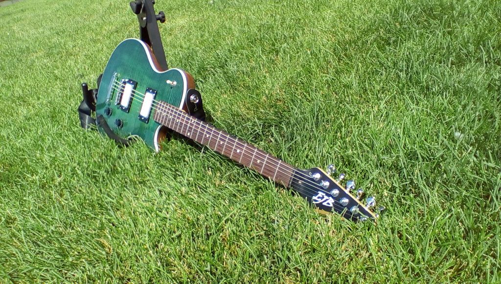
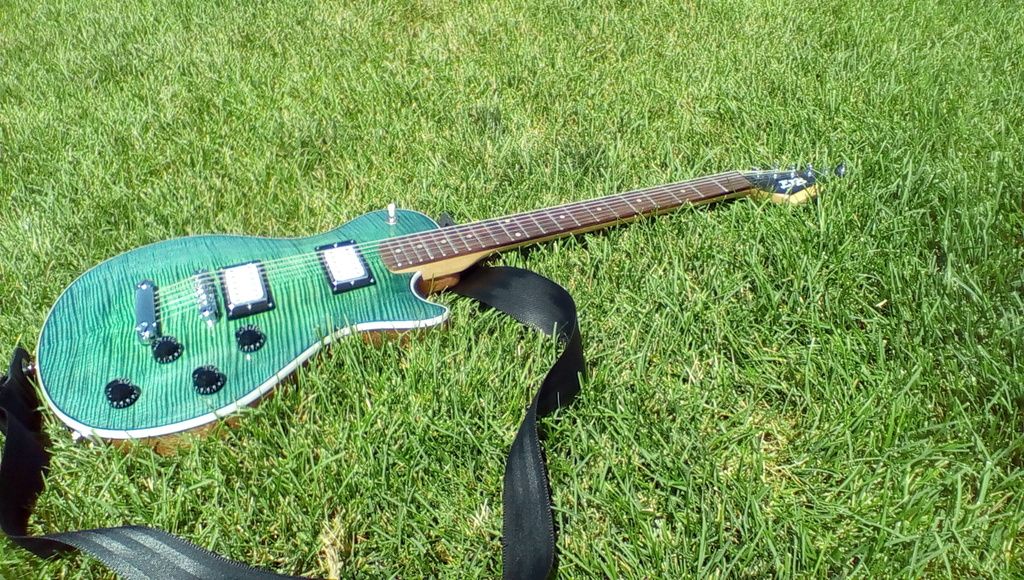
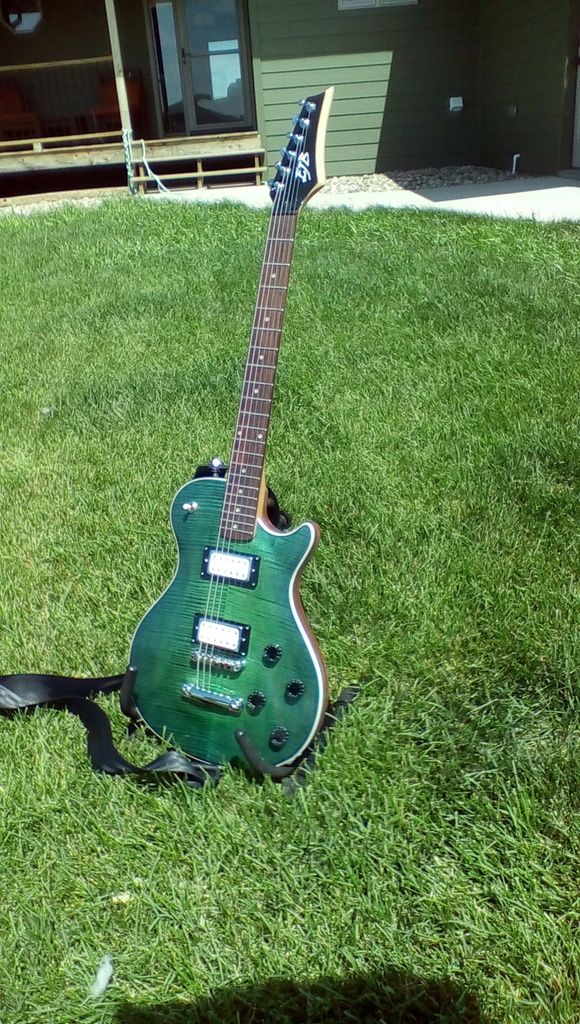
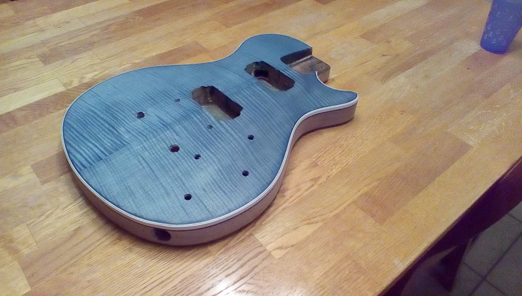
Here's the resulting guitar. still have to finish up the model of the trimmer...
Took some nicer pictures today. That figure really pops at the right angles!

-
1
-
-
Is there anything in there for different nozzle sizes? I haven't been able to find it and I have a larger opening in my nozzle. (sounds like a bit of a personal problem there..)
-
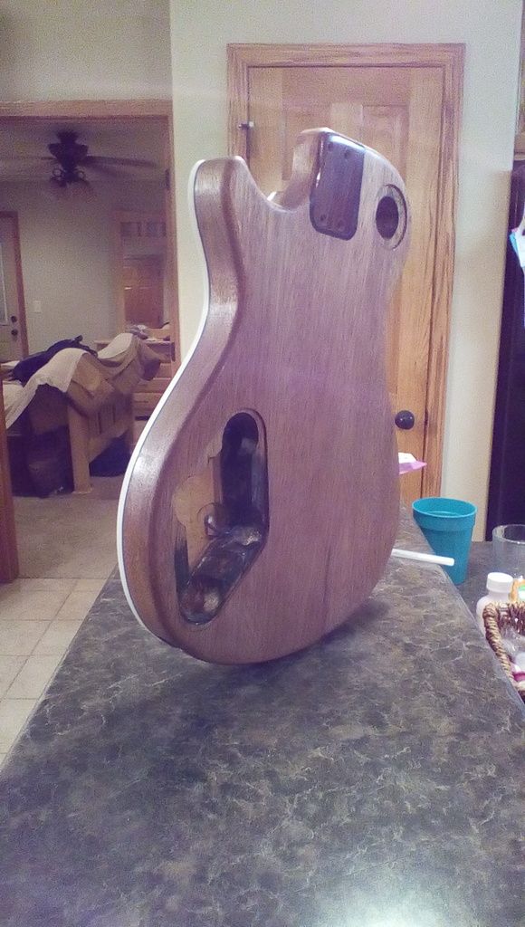
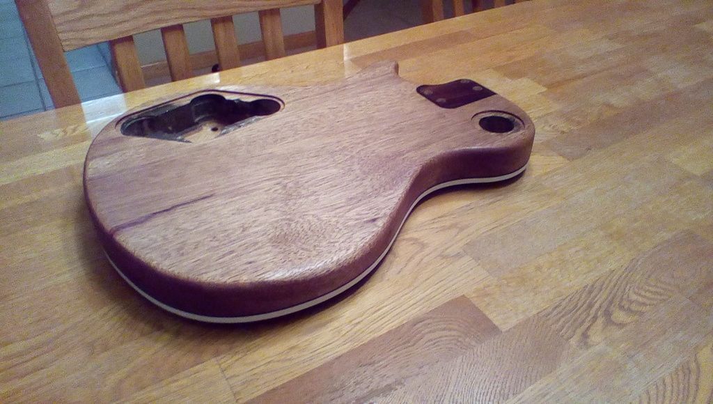
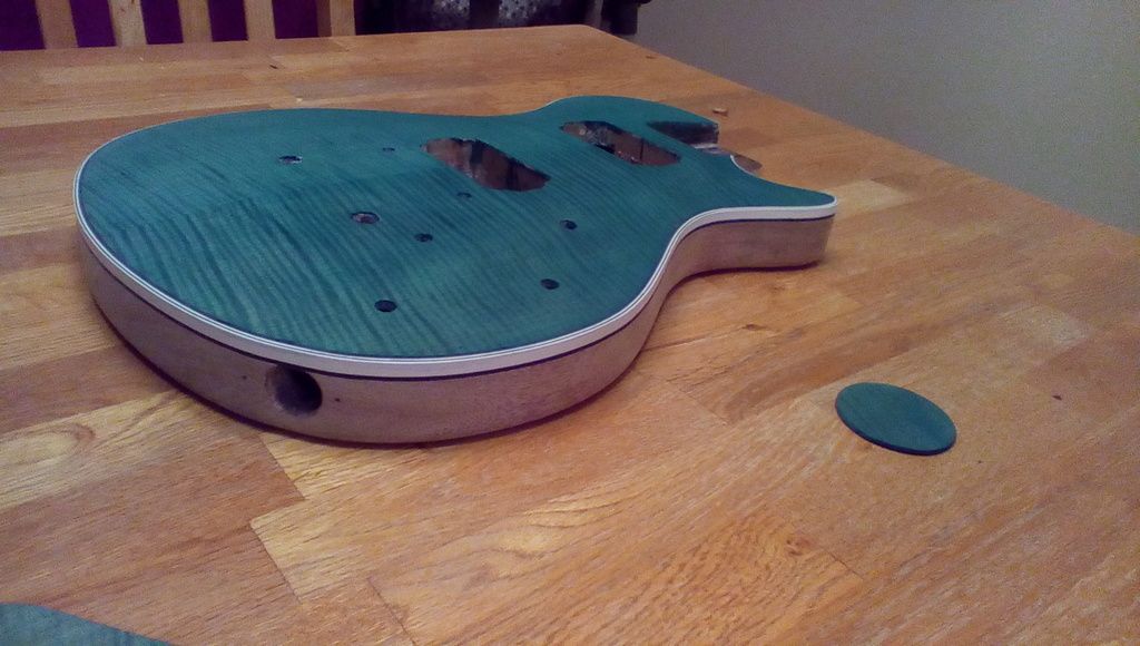
Some clear shellac on the back to seal it up. Now to fill the pores!!
-
1
-
-
Just have to finish putting the hardware in it I in the model
-
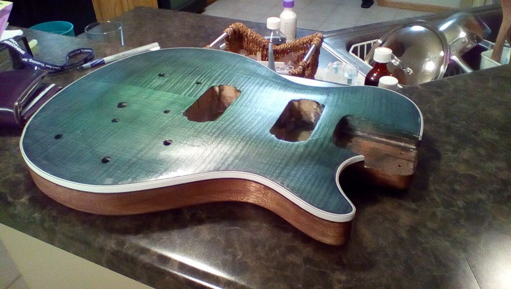
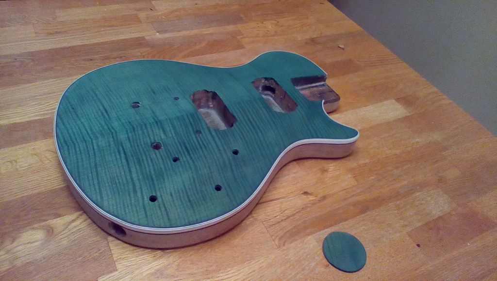
Second coat was a bit darker than I envisioned but I like it. Should have made the green dye a bit thinner.
-
1
-
-
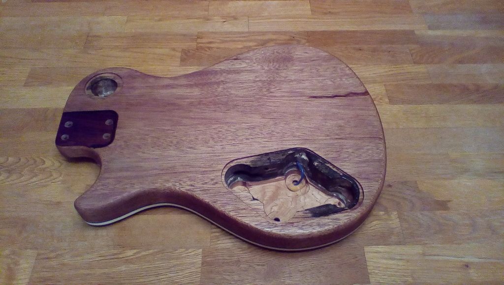
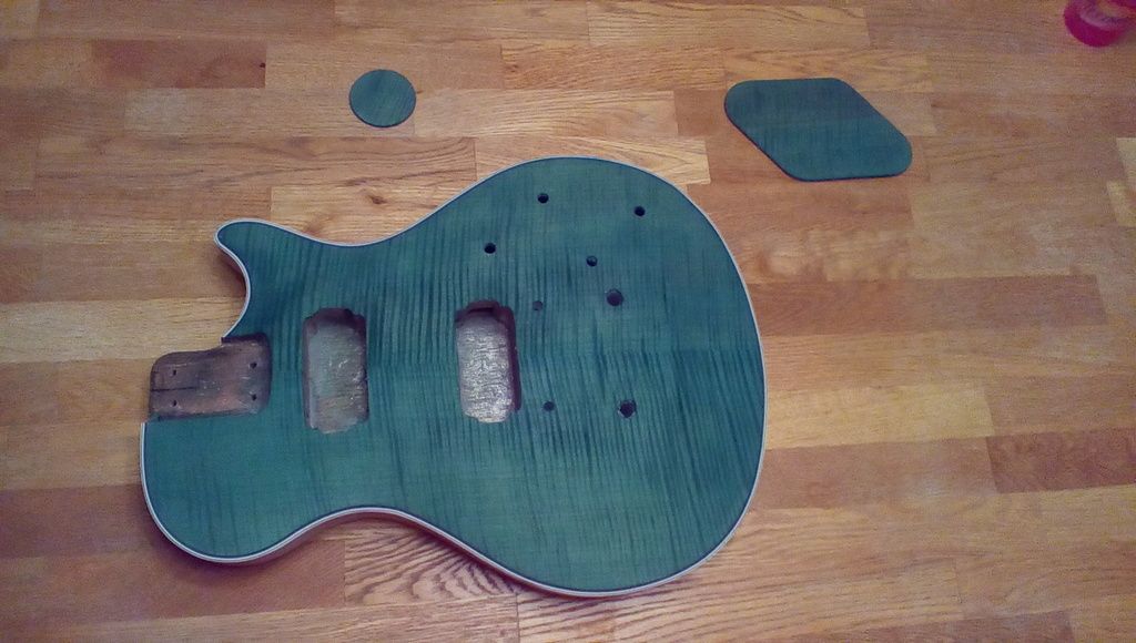
I'm re-working a guitar that I built a couple of years ago. I have glue'd a really nice piece of flame maple veneer to it using a vacuum bag that I made from scrap at our engineered films division and I have put binding on it in order to hide that it is a veneer top and to protect the edge. I decided to print some of the tooling for doing this. I made 2 dremel attachments. One of them for cutting the binding channel on the edge of the guitar and another for trimming some ABS strips into thin pieces for additional decorative strips on the edge of the binding (called purfing).
I have not taken pictures of the attachments themselves but I do have screenshots along with solidworks models of the parts/assemblies.
Printing the parts probably saved me from buying around $150 worth of tooling to do this.
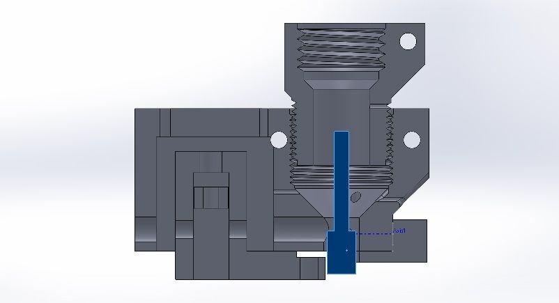
Here is a cross section of the binding trimmer with the dremel router bit highlighted blue. The binding passes through the little slot to the left of the bit where I trim it a bit at a time by adjusting a screw. A spring loaded piece maintains pressure to keep the binding piece against the adjustment guide.
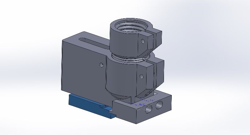
And an isometric view. The top piece attaches to the dremel and is clamped in place. I have an extra part in there because it is based on my binding channel cutter where I added another threaded portion for depth adjustment once the tool was attached to the dremel.
And for fun, here's the guitar in process. It has the first coat of dye that will get sanded back to leave the dye in the deeper figure then I'll put a lighter green/blue dye on to get a nice color combo and really make the figure pop.
-
3
-
-
It is probably not strong enough to handle anything but the easiest materials to cut. If you wanted to cut some visualization type prototypes from foam block that might work.
-
I've been using the airhockey puck slurry method for a while now with good success. I have a bulb eyedropper that I use to drop some acetone on the plate, and then swirl it around with an ABS puck. Easy and it works well.
-
I made a bunch of small clamps for laminating the sides on a guitar case.
-
the bearings for the carriage would have to have the splined shafts on one side as well. They would transfer through a gear set within the carriage.
Maybe too much added complexity and it might be simpler to go with a small stepper on the print head with a gear reduction.
-
@muttstang: Are you sure? You seem to be describing flexidrive. It uses a speedometer cable to drive a head mounted extruder. What is different about your idea?
My thought is more that the rods that the print head slides on would be splined shafts and they would rotate to drive an extruder mounted in the print head. You don't have a seperate component going into the print head to provide rotary motion. It is part of the bearing/rod system.
The thomson version is probably a lot more spendy, but there are others out there that might not be to bad. It would add to the cost but it would put the extruder in the head without the added mass of a motor. You could put one on the X and one on the Y and rotate them independently in the event of dual extrusion.
http://www.thomsonlinear.com/website/com/eng/products/ball_screws_and_lead_screws/ball_splines.php
or
http://www.nbcorporation.com/product/lineup/ballspline/ball_spline.html
-
Have you guys ever considered showing off your stuff at Solidworks World? There are many many professionals there who would likely be interested in another 3d printing option.
That's where I picked up an UP! plus and got into 3d printing.
-
Oh, I know about the flex drive. my thought is something a lot different
-
the splined shafts tend to be spendy, though if a decent sized manufacturer is making a run of 3d printers, they probably can get a good discount. the build it yourself types will have to scavange ebay a bit more to get the same thing.
Or use square shafts and needle bearings like the original poster in your link.
-
Not really something to be fitted to the UM2. But are there any 3d printers out there that have used a splined shaft on the X and Y to transmit rotary motion into the print head? That rotary motion could drive an extruder.
-
Printed a pair of idler pulleys out for the cnc router to replace the wobbly ones that were causing my x-axis screws to whip around badly. It definitely helped! I'll probably print some ABS pulleys out later as the garage may get a bit warm come next summer for the PLA to survive.
-
I'll be trying some out as idler pulleys in the garage. the machined pulleys I made wobbled something fierce and were making the X-axis on my router whip like crazy. Hopefully that smooths things out a good bit.
-
Got the UM2 in yesterday. That was a nice surprise to find at my cubicle..
It took a bit longer then the 5 days to ship, more like 9. Not a huge deal but communication could be better to give an estimated ship date and follow up with a tracking number.
Otherwise it has printed well so far other then 1 failed print that probably was a result of me trying to mess with the advanced settings.
-
and a surprise coming back from lunch to find the UM2 sitting behind my chair...
-
CNC router update:
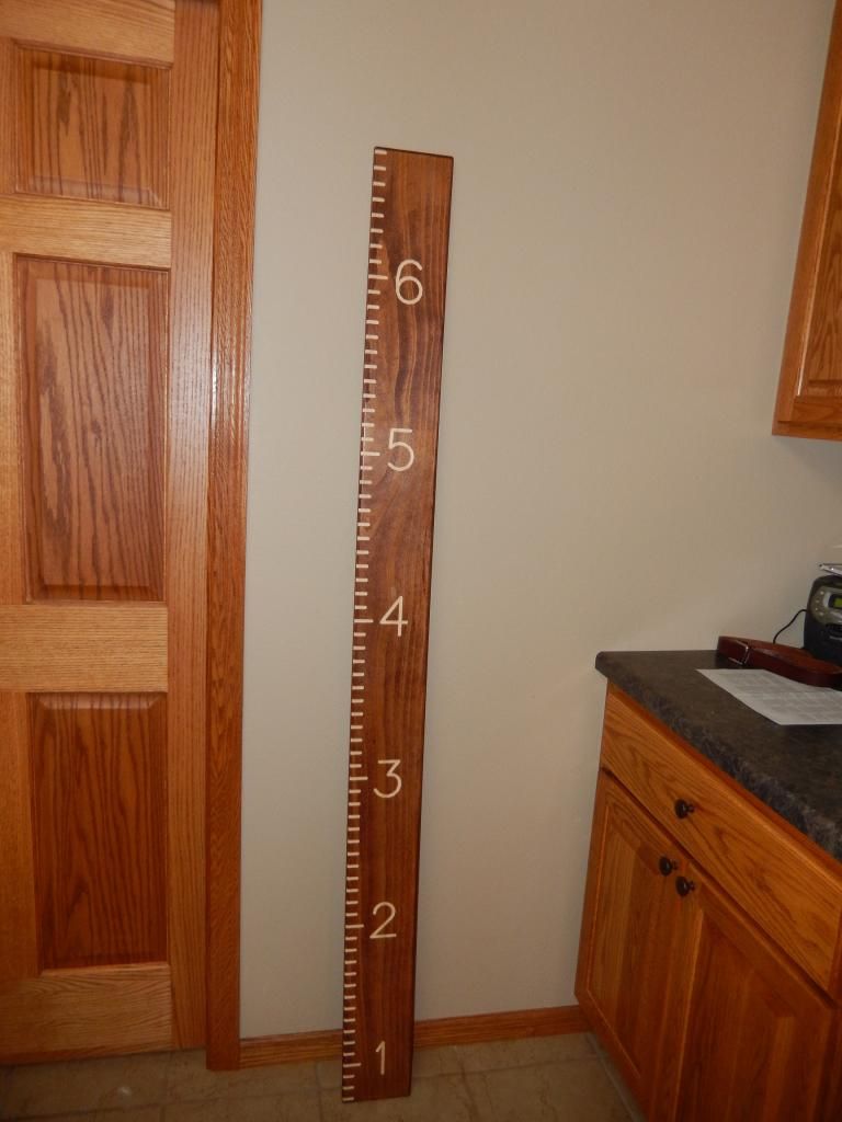
Made my first cuts today
 A big ruler to measure the boys as they grow up. Got the machine running pretty slow at the moment. I really want some multi start screws on the X axis now!! I get a bit of whipping with it as it sits if I crank the speed up too much.
Kept it simple for the first thing made.


 A big ruler to measure the boys as they grow up. Got the machine running pretty slow at the moment. I really want some multi start screws on the X axis now!! I get a bit of whipping with it as it sits if I crank the speed up too much.
Can I edit the e-steps on my UM3?
in UltiMaker 3D printers
Posted
The parts coming off of our UM3 are different in the X and Y axis. For example. I have a round part here that's 1.255" in one axis and 1.233" in the other axis.
Is there a way to correct this differently in the X versus the Y direction? I'd just update the e-steps on my DIY printer.
Thanks!