


shiremog
-
Posts
67 -
Joined
-
Last visited
Content Type
Forums
Events
3D Prints
Posts posted by shiremog
-
-
Thanks for the tip. It appears that I'm on the right track then. What material is the bowden tube? Looks like standard 6mm nylon pneumatic tubing.
-
I ask 'cause I'm getting carry-over of a previous filament, causing coloured streaks. Some of it is from the outside of the nozzle where I haven't cleaned it properly :roll: , some I believe is stringing in the bowden tube, but I suspect that some is trapped in that ridge inside the nozzle.
-
Looking at the drawing of the UM2 nozzle, I notice a step at the bottom of the angle ( on the inside of the nozzle) where the 0.4mm hole comes through. Is there a reason for this or is it just the way it's made?
-
Just what I was looking for. Thank you.
-
Can anyone point me in the direction details of the ultigcode?
-
Ah. Thank you.
-
Yes, I see this on the tooltip, but how do these speed settings relate to the speed setting in the "Basic" page?
-
I'm confused!
In the "Basic" page of settings there's a "Print speed setting". In the "Advanced" page, there's a range of speed settings. Which applies? How do the settings on the two pages interact?
-
You are creating images so you should be looking not at CAD software but maybe microsoft Word (if you have it) which has a "word art" feature which can bend text into an arc like this with any font. Or photoshop which can easily blend the edges of the text into gray regions. I'm not sure how to bend text into a circle pattern like this easily in photoshop.
I use inkscape. Dead easy to bend text. Enter the text normally. Add the curve you want. Select both the text & the curve & Text->Add to path.
-
Ugg. It's all very simple math. Lets say you use 50% gray for the color around the text. Lets say you want a base of B (in mm) and a total height from top of letters to bottom of A (in mm). Here's how you do it:
when importing the image set base, height, and cutoff values depending on formula below...
A = cura_base+cura_height - cutoff
B = cura_base+cura_height*0.5 - cutoff (0.5 comes from 50% gray color - change to 0.1 for 90% white color etc.)
cutoff must be > cura_base
Solving backwards...
A-B = cura_height*0.5
cura_height = ( A - B )*2 <-- this is mandatory - the only absolute
set cura_height to ( A - B )*2
calculate base_minimum = B - cura_height/2
if base_minimum<0 then use cura_base=0 and cutoff= -base_mininum
if base_minimum>0 then use cura_base=base_minimum and cutoff = B - cura_base+cura_height/2
Example:
I want B=2 (baseplate thickness) and A=5mm (total thickness)
set Cura height to ( A - B )*2 or 6mm (set when importing image)
cura_base to 0mm (set when importing image)
cutoff = cura_height/2 - B = 6/2-2 = 1mm (set in advanced quality settings)
It's easier to do specific examples than to do the formulas. Just remember your cura_height should be set first based on grayscale level and difference in desired base height versus text height. Once that unknown is solved the last two are simple.
Ah! I understand ( I think). You are not using a base, just using the black/white contrast to set the overall height & the greyscale to set the depth of the text. Clever :???:
Thanks for taking the time to explain.
-
No. You don't get it. The reason you print *gray* around the letters is so that the curved part is HIGHER than the rectangular base. Then you use that "cut off object bottom" to cut off the rectangular part but *not* the curved base. Just try it - put a 50% gray around the letters - in the curved section.
You can also create a slope to the letters by blurring the edges of the text slightly and having that be a dark gray. Although you say Cura already takes care of this.
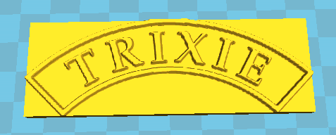
I understand what you're saying. Here's what I get:
So yes, I've lost the rectangle, but I've also lost the base, so the model iis too thin to use as a pattern :-|
-
Those letters do have a draft of 10 degrees

You could always add some fillet as well to smooth sharp edges. Anyways, it was just an attempt to illustrate how quickly you could design one up, and there are several free CAD programs available, if price was an issue.
I use Varicad. There's no easy way to add draft to text ( in fact it's quite a long process to create 3D text!) Inventor, again, is windows. Perhaps I need to look more at modelling software rather than cad.
-
I thought at first that Cura had an easy way to produce these name plates but it seems that it will only do rectangular plates. The problem with modelling is that each vertical side ( including the sides of the letters ) need a draught ( a slight slope ) to allow it to come out of the sand. The way I've achieved that to date is with a CNC mill using a tapered cutter. The smoothing function in Cura produces the draught beautifully with Light Smoothing. All I need to do is run a file over the outside edges.
-
Trouble is, I need the base & that's what causes the rectangle ( I'm using Height 1.5 & base 4 ) & that's what I want to follow the profile of the border. If I cut off the bottom, I just cut a bit off the base :-| .
I could do as you suggest then print a seperate base from another model then stick them together, bit it would be good to print it all in one.
( the object of the exersise by the way, is to produce patterns for sand casting name plates )
-
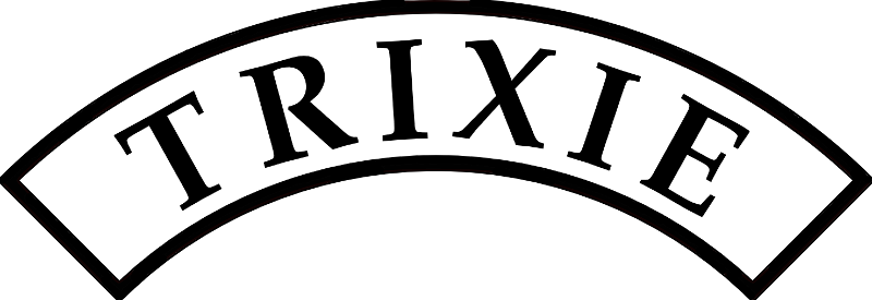
Thanks for the instructions, cool dude :wink: , but that's not what I was after. Here's a picture of a name plate for a model steam traction engine:
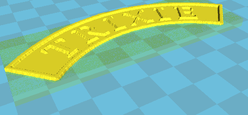
Here's what Cura produces:
I want the model to follow the outline of the name plate.
( by the way, mine is a microsoft-free home, so I couldn't have used zsurf anyway :-| )
-
The method of making a model from a picture ( jpg, png etc) in Cura works very well. Using Light Smoothing of a peice of text in bitmap form gives a nice amount of draft on the sides of the lettersm aking an ideal pattern for green sand casting. Ideal for name plates & the like.
Two limitations I find:
It would be good to be able to vary the smoothing to allow for varying text sizes, rather than the three steps available at the moment.
Making shaped models dosn't appear to be possible. The result always comes on a rectangular base. Has anyone found a way around this? I want to make some curved name plates but I would then have to cut them out from the base. This would also mean that I'd have to print the models solid otherwise the hollw internals would be exposed.
Ian

UM2 nozzle
in Coffee corner
Posted
So it does appear to be a design feature. I was thinking about making a replacement without the step, which I reckon would reduce the carry-over & reduce the chance of a blockage, but perhaps it would cause another set of problems. Has anyone tried it?