


ekh
-
Posts
18 -
Joined
-
Last visited
Content Type
Forums
Events
3D Prints
Everything posted by ekh
-

UMO PID formula error, UMO heated bed upgrade low nozzle temp SOLVED
ekh replied to ekh's topic in UltiMaker Cura
Thank you for helping :-) The BANG_MAX is in use when the reguation (e.g. during initial heating) is not used or outside bounds if I got it right, while PID_MAX is the max PID output during regulation. So you are right that both values must be changed, if I will use the (weak) original power supply again. But because the PWM frequency is so low, maybe the power supply will fail anyway within the time the PWM pulse is on. -
UMO PID formula error, UMO heated bed upgrade low nozzle temp SOLVED
ekh replied to ekh's topic in UltiMaker Cura
You are right. Somehow I wanted to multiply before summation, but the official formula sums the error and multiplies afterwards. I suffered from the end of life heater and "now it works" syndrome, instead of going more thorougly through the code. Please acceept my apologies for having wasted your time. By the way the 4ohm heater element draws too much current for the power supply, it resets randomly within the first few minutes of a print. I also added the suggested change to the FET driver circuit, to avoid problems with the FET driving the low ohmage. After replacing the power supply with a 480W supply, the UMO has worked like a charm the last 72 hours. On the plus side it heats the nozzle approx. as fast as the UM2. But I still nedd to print 2 * 500 hours to finish my order. That is why I want to build 10 printers myself with a little bit better properties for 24/7 printing, e.g. end stop on filament. My next order is 3000 hours of printing. But again thank you for being thorough and checking me. -
UMO PID formula error, UMO heated bed upgrade low nozzle temp SOLVED
ekh replied to ekh's topic in UltiMaker Cura
Let me quote myself: This was correct, but it was not the supply woltage, but the nozzle heater element that was worn out. The resistance was 10ohm I checked that even when the FET was on all the time the temperature was too low. The printer has for long periods worked 24/7 and the heater element has been worn out. In another post I blamed the FET because it has failed once before, but not this time. Another heating element I bought for making my own printer is only 4ohm. So the loop amplification was more than halved (10/4 = 2.5 times assuming the original heater also was 4ohm). That is why I was the only one suffering from the error in the PID formula. -
One more thing caught my eye. The 3 instrumentation amplifiers ( INA826 ) for the PT100 sensors are loaded too much capacitively. The datasheet says: Any amplifier with feedback is a regulating system in itself, where the bandwith and loop gain must be designed to have a sufficient phase margin at gain = 1 to avoid noise, or worse that the amplifier acts as an oscillator. The ouput are loaded with 100ohm in series and 10nF in parallel. 10nF = 10000 pF. Even with 100 ohms in series, the instrumental amplifier is loaded too much and challenged to keep stable. The ADC input on the ATmega2560 has 100Mohm input resistance, so using 100ohm is not necessary. I will suggest using 2k2 near the amplifier output and 1nF near the ADC input pin. That will reduce the stress on the output stage in the amplifier and probably also reduce the noise on the temperature readings.
-
One more idea. If all the linear bearings were adjustable, then we can minimize free play and get a better print quality. It can be made as an upgrade. New bearings and plastic parts for the printhead, and replacement bearings for the buildplate.
-
Undesired horizontal ridges on regular distance
ekh replied to maartenw's topic in UltiMaker 3D printers
Thank you for your thoughts :-) I have not thought of uneven lowering, as I expected the vertical linear bearings to be OK. So I tried the free play on both my machines, and there was a free play sufficiently large to be a factor in the print quality. I do not agree that 2 spindles will be the solution, because the angle precision of a motor step and uneven spindle picth could be a problem in itself. I think the solution is adjustable linear bearings like this example: http://www.ebay.de/itm/x4pcs-ID16mm-Adjustable-Linear-Bearing-LME16UUAJ-CNC-/221455576263?pt=LH_DefaultDomain_3&hash=item338fc7ecc7 As the link disappears in time I post a picture here: This could be made as an upgrade to replace the existing vertical linear bearings. Free play on the x y bearings will also result in banding. I have seen that manufacturers also produce 6 mm adjustable bearings. If we had adjustable bearings, we could minimize the free play without increasing the friction. We could also adjust from time to time to compensate for wearing of bearings and axles to a certain extent for the axles and full extent for the bearings. Adjustable bearings are attractive, I will post that in my thread to keep these ideas in the same place.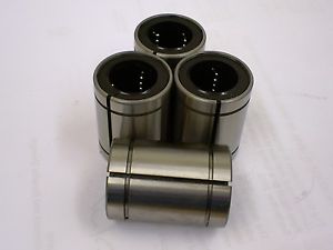
-
Hi again, Every bird signs with its own voice. Maybe I'm not the most diplomatic guy, I focus on the possible solutions. Please read the following in the positive spirit it has been written. I got triggered to make this post because my UMO does not regulate again, this time it is not the "UMO PID formula error" but the FET transistor driving the heater. So it will be the second time I have to change this FET. I looked into the diagram of the UM2 to see if the cause of the failing FET has been corrected there. It was unfortunately made the same way. The curcuit is an AVR uC pin driving the FET gate through a 100ohm resistor. This is not a good way to do the job. This is basically a RC circuit. When the pin goes from 0 to 5V in a short moment there is 0 volts over the "gate capacitor" thus giving 5V or something near over the resistor. 5v/100ohm = 50mA. According to the AVR ATmega2560 datasheet, the absolute maximum rating for a pin is 40mA. From my experience exceeding specs has never been rewarded with reliability. I have made approx. 30 designs with AVR processors since 2001. A good rule of thumb is to be at 50% or below of max ratings. This means that the resistor should be 270ohm. The FET will not like that, because of increased thermal stress due to long switching time like on my UMO. I looked at the pcb layout, and fortunately there is space to solve this properly at a low cost and little effort, as there is pcb space available for 3 drivers. In order to make a FET swith properly with low switch losses we are not talking milliamps but Amps of driver current. The MOSFET gate driver "ZXGD3004E6" is able to deliver up to 8 amps of gate driver current. It is very compact in a SOT23-6 case. I have used this many times and it works well. Here is an example: Here the L6387 is a bit too weak to drive the FETs properly so the ZXGD3004E6 assists. In your case replace the L6387 pin 5 with the uC pin and suppy U5 with 5V instead of 12V. R18 can then be 220ohm and R17 and R19 can be selected for your taste in driving the FETS on the UM2. This is a tested and functional circuit. I will recommend you do a change like this or better, if you find a better solution. Like my UMO has failed twice, the UM2 will fail also eventually. After all we are here to print, not to repair. --- One of the first things I learned after I graduated, was from an older engineer. He said that whenever you use a mechanical switch, be sure to draw 5 mA through the contact set to prevent unreliable operation due to oxidation. The 5mA keeps the contact set clean without wearing it down. I have never seen this mentioned in a book, and nobody told us at the university. Since I have repaired many "temporary" button problems by adding resistors. I will recommend you add pull-up resistors to the 3 contacts in the rotary knob, and also the card detect and the other switches get a smaller resistor in order to draw 5mA, i.e 1Kohm instead of 4K7. --- I have a suggestion for the feeder wheel. I would like to have a knob on the wheel so I can feed filament manually like on the UMO. The stepper motor is so weak that you can turn the knob easily. ---- The very nice stainless steel thermal isolator, has only a few threads at the bottom. It would be nice if the nozzle also had just a few threads near the block with the heater and temperature sensor. Then there no longer will be the need of so much turning and turning and turning..... to disassemble and assemble the nozzle. --- The heated bed is all too weak mechanically for my taste. I have seen resonance with approx. 1 mm amplitude on the UM2 caused by the UMO printing next on the table. I have seen up to 0.5mm bed amplitude measured at the front leveling screw when printing overhangs. This was measured with a dial gauge with 0.01 mm resolution. I am going to make the heated bed mechanically more stable on both printers. It would be nice if you changed this. It will surely reduce banding effects due to vibrations generated by the printhead causing over/under extrusion. --- I would prefer a design with shorter distance between the x and y axes and the nozzle tip to minimize the position error due to free play in the linear bearings. --- Each toothbelt introduces a positon error. I would prefer a design with stepper motors driving the rotating axle directly to eliminate half the position error. --- If you made it to here, thank you for caring :-)

-
Thank you for caring :-)
-
You can check if the fans cool sufficiently. Make a tweak to pause the print and park the head so the nozzle is free of the part but a fan sends air over the part to cool it. Wait half a minute then resume printing. Try 3 tweaks for each 2mm print height, if cooling is the problem then it will look better in that area. I have printed small buttons, and they easily looks like your print wihout reducing nozzle temperature and increasing min. layer time. It can also be a bad quality filament, or the filament contains water that makes the plastic expand after being printed due to many small water wapor bubbles in the print.
-
I have designed a product with 13 pcs 3D printed parts taking 60 hours to print. Several of the parts are not economically feasible for me cast in plastic, as the molds will be much too expensive. As I want to "mass produce" the product I need many printers in our newly started company. So I bought 3 pcs of this as a start: http://www.ebay.de/itm/SainSmart-Ultimaker-Mega2560-R3-LCD-12864-Controller-Similar-With-Ramps-1-4-/231172221638?pt=LH_DefaultDomain_77&hash=item35d2f02ac6 I have looked into config.h but there are so many options that I gave up after an hour where the best attempt led to a compile error. I have installed the U8glib library in the Arduino IDE 1.6.5. Hopefully one of you have solved this already. I will be very thankful for an advice that makes it compile and the graphic display to function. That will enable me to produce the printers I need. I have no intention of selling printers. Instead I will share the design here, if I get success in making a good printer optimised for my parts.
-
Undesired horizontal ridges on regular distance
ekh replied to maartenw's topic in UltiMaker 3D printers
Thank you all for many insights, I have this problem on both the UMO and the UM2. Thinner layers increase the problem. As I see it gr5 is right: "Your z movement is not linear." The result is both under and over extrusion. When you have a sledge, there will always be some friction resisting the movement of the sledge. When you have a screw and a nut, you must have some free play, else the nut is stuck on the screw. When the buildplate is lifted, the direction of movement is always against the friction, so the play does not disturb accuracy. The vertical arrangement has two possibilities. -The weight og the sledge gives a downward force able to overcome the friction so the play is always in the same direction. -The weight of the sledge is less than the friction, thus the sledge stand still until the screw has turned so much the play is gone in the other direction. Then the screw "pulls" down the sledge opposed to the sledge "falling" constantly from the very first movement of the screw. So I added 400g of weight near the back of the buildplate, to get more force to overcome the friction, and it reduced the banding. Another option is the rebuild to get less friction, a better solution, but also more time consuming. -
It seems to me that the cooling is not sufficient. Maybe the nozzle temperature is too high, Also consider the minimum layer time in Cura
-
I have had an UM2 for 2 months now, I have some suggestions to the production of the UM2. But first I have to say that you guys at Ultimaker do a great job IMHO. It is no easy task to start a company and grow as fast as you have and keep everything perfect. Also the way you selected for your busyness model is very positive and along what is suggested here: http://www.thrivemovement.com/the_movie I recommend you watch the Thrive movie. If you have no knowledge of the issues the movie puts light on, watching the movie can change the life quality for yourself and others in a positive way. The planet needs change. But back to the subject. --- My first comment is: Do you make "burn in" of the printers. The display on my UM2 failed after approx. 6 hours of printing, I returned the UM2 to the shop where I bought it, and had to wait nearly 2 weeks to get it back. Electronic failures follow a "bath tub" curve where many fails occurs in the first hours of operation. Then follows a hopefully long period of a very low failure rate. Eventually at the end of product life, the failure rate goes up again. I will recommend that when you have assembled a printer, you set it to "print" 48 hours in 40 degrees C room temperature and no filament. The "part" contains movements and nozzle and bed temperatures as when printing for real. If it stil works OK after the 48 hours, you insert filament for the first time and do a real test print before shipping. If it does not work, you have saved a customer from an annoying experience and you can correct the problem at the lowest cost. --- The axles supporting the print head were not parallel to the rotating axles. The errors were 1 mm and 2 mm for the two axes. That part of the assembly ought to be done better. --- The X motor is not mounted sufficiently accurate, so the toothwheel grinds the toothbelt so that rubber smudge falls down on the x motor. A guy in the shop has also seen this, so it is not only my UM2. Apart from reducing toothbelt lifetime, this extra friction does not improve print quality. --- The tootwheels are too bad a quality, the holes are too big for the axles. When the screws are tighthened, this results in excentricity giving an position error depending on the angle of the wheel. This was also the case for my UMO. --- The tolerances for the linear bearings in the print head are not acceptible. In one direction the play at the tip of the nozzle was 40 to 50 um. I'm taking of free play here, not forcefully bending something. I could not find long 6 mm bearings on Ebay, so I bought 8 short bearings and selected the best 4 bearings. I measured the existing head and made new drawings for the black plastic parts in order to use 4 short bearings instead. After printing the new parts, I replaced the plastic parts and the bearings. That improved the print quality. I have attached a 3D view of my new printhead. I could fiddle more with the tolerances, but to me this is not a final solution. I am in the process of designing a new print head with the extrusion feeder in the head, using 1.75mm filament. Designing a 3D printer is a big compromise, where you have to select specific solutions. There are many good choices in the UM2, but for the printhead I disagree. I expect the new design to weight only slightly more than the existing moving parts. I will do my best to solve many issues about print quality with this head. It is no easy task with risc of failure, but if I succeed in making something useful, I will share drawings and STL files here. I will make another post about this subject later. I have attached a 3D view of the intermediate printhead design.

-

-
I can't say, sometimes you are fighting more than one error at a time. But adding noise near the amplifier can be the problem. What I can say is, that when operated within specifications, parts from Analog Devices do an excellent job. It is one of the most skilled producers of analog IC's. I have added a picture showing the pcb on the UMO printhead, where an extra 1uF ceramic capacitor has been added upon the original C1. On my UMO I have seen no temperature noise since this addition.
-
Thanks, it was a temporary error coming from time to time, had to discard the print each time it occurred. Hope it can spare others from from this annoying error.
-
Hi, I have an UMO with heated bed upgrade. After the heated bed upgrade was intalled, the temperature regulation was not able to keep the setpoint temperature, but it typically was 20 C too low. The probable cause is insufficient total loop amplification due to a bit lower supply voltage due the the load from the heated bed. It could also be changes in the sw for the upgrade. I have not digged into that. But no matter how high I set the integral value it was not able to regulate correctly. I looked at the newest firmware (Github checkout 2015-0704). The problem is that Ki is not part of the PID formula. In the file temperature.cpp, change line 438 from: temp_iState[e] += pid_error[e]; to temp_iState[e] += Ki * pid_error[e]; With PID constants: Kp = 16.67 Ki = 2.00 Kd = 114.00 The regulation works as it should, I have not spent much time finding these constants, so they are probably not optimal, but they are sufficient to make it work. Ekh
-
Hi, This is my first post. I have had an Ultimaker Original for a year and an Ultimaker 2 for 2 months. On the UMO I have experienced noise from the amplifier pcb on the printhead. It resulted in arbitrary "fishnet" layers due to too low temperature caused by temperature noise. The cause of the problem is an unstable supply voltage for the operational amplifier. When you have a pcb with many IC's and low inductive supply planes, then a 100nF decoupling capacitor for each IC do a good job. But the pcb on the printhead sits in the end of approx 1m cable with self inductance. I soldered a 1uF ceramic capacitor on top of the existing decoupling capacitor, and have not had this problem since. IMHO the thermo couple solution is superior to a PTxxx solution. Ekh


