Jump to content

Introducing The Experimental Bridging Settings


burtoogle

Recommended Posts

Posted · Introducing The Experimental Bridging Settings

@smartavionics:

based on your idea of a support-bridge below the real bridge, I did a few more experiments for single-sided overhangs, like roofs and flanges.


This concept seems to work reasonably well for straight walls. It is better to have a few little defects in the shadow of the roof, than to have supports all the way down to the floor, and damaging all items in-between on the walls or the floors. I don't know the English terms, but in Dutch: vensterbanken, luifels, raamkozijnen, luiken, keldergaten,... In this test model I printed text on the floor, so I don't want to damage this text with supports.


Keep in mind that the table-model is small: all walls = 1mm thick; stairs in the support = 1mm x 1mm; gap between vertical walls = 1mm. Connecting strands between model and support = 1mm long x 0.5mm wide x 0.2mm high. Gap between ribs on top and underside of table = 0.3mm.


This works well on my UM2 for PLA, printed at 50mm/s, 210°C; or printed at 25mm/s, 195°C.


For dual nozzle systems like the UM3, you could fill the gap between the ribs on top of the support, and the table-underside with PVA-support. The ribs would give a sort of dove-tail effect and improve bonding of PVA to PLA. At least, I would guess so.


For circular walls like flanges on pipes, this method is not yet good enough, because when drawing the outline circles of the flange, the filament cuts the corners and draws a straight line instead of following the edges.


overhangtest11c2.thumb.jpg.a46d23123127b77f81082a2efa4daa80.jpg

Basic concept: supports connected to side walls via tiny strands. No connection on top (gap of 0.3mm). Gap between supports and side-walls is 1mm. Connections are 0.5mm wide x 0.2mm high.


overhangtest11e.thumb.jpg.1f92bf0e3eb064e1d9edbdf9edd16b3c.jpg

Don't want to destroy the text by supports going all the way down (for single nozzle printer).


overhangtest12c.thumb.jpg.66413fb43b5cc730373f71f08226706c.jpg

Same idea for flanges. But the supports need to be in segments, otherwise we can never get them off.


overhangtest12c2.thumb.jpg.0fad6062740cb54cfc2441957b8275eb.jpg

Cut view.


DSCN5727b.jpg.8aeeef6796d24bf7adbbdaa5eb24f52a.jpg

Results: colorFabb PLA/PHA (natural), printed at 210°C and 50mm/s, thus rather fast and hot for such a small model. The method should work in less than optimal conditions too.


DSCN5749b.jpg.a1d2ca69fc45ddf1671be5f91d1bb54c.jpg

A little bit of damage to side walls after removing support, due to the connection strands.


DSCN5751b.jpg.83314ceaef2ec8232c901f14cca77733.jpg

After a bit of cleaning with a sharp knife, the result seems pretty reasonable. And the table underside is okay, as good as it can get on a single nozzle printer. Remember: all walls are 1mm thick, nozzle = 0.4mm, text = 3.5mm character height, 0.5mm line-width, and 0.3mm raised.


DSCN5736b.jpg.6c85384d187d9e14552443bcf307418f.jpg

Removing supports under the flange. Flange itself is rather ugly and irregular.


DSCN5757b.jpg.d59ac738aed262f7b194556d2b43a9f8.jpg

When printing the flange, the filament did cut the corners (straight line from hole to hole), instead of following the outline of the circle. So this created an irregular flange. Not good enough.


support_sandwich.thumb.jpg.e42b127a279f4a760c444239c73a086c.jpg

Idea: for dual nozzle printers and PVA-support: when using a combination of support in PLA, with a buffer layer of PVA in-between, the connection between the PVA-support and PLA-support could always be done with such a dove-tail. This should make it bond well.


DSCN5751b.jpg

  • Like 2
Link to post
Share on other sites

Posted · Introducing The Experimental Bridging Settings

Forgot the STL-files for those who want to try it:

overhangtest11e.stl (=table with supports)

overhangtest12c.stl (=pipe with flanges)


(Note: there is definitely a bug when inserting images: in my previous post, I did not include the last image. The system duplicated it itself. And I can't remove it anymore.

Most of the time inserting images goes best when dragging and dropping them from the Windows explorer into the desired place in the text. But here one went wrong...)


  • Link to post
    Share on other sites

    Posted · Introducing The Experimental Bridging Settings

    Hi @geert_2, that's all very interesting. I definitely think there will be situations where these techniques would be valuable. I am happy to keep working on the bridging support in Cura so if we need some changes to make a better result, please don't hesitate to make suggestions. Great work, thanks.

  • Link to post
    Share on other sites

    Posted · Introducing The Experimental Bridging Settings
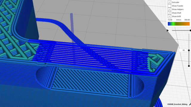
    On 27/03/2018 at 4:47 PM, smartavionics said:

    Here is the first bridge layer, I am showing the layerview as feedrate so you can see the speed changes on the bridge. Notice also the coasting just before the bridge walls start (the walls are printed anti-clockwise):

    Screenshot_2018-03-27_14-52-43.thumb.png.d3bd9ada0b26d474d5d75aeec3251a15.png


    I am very pleased to finally have some settings for bridging to tweak! I have been playing around with them and getting some pretty good results.

    I was wondering something about the image above. The bridge lines in the image seem to extend into the infill, while mine will only start from the underlying walls. It seems useful to me to extend the bridge beyond the walls, but cannot find a setting that controls this. Also, my bridges are surrounded by wall lines, where the ones in the image are not. I don't think this matters a whole lot, but I am still wondering why I am having a different result. Any tips?


    bridge example.jpg

  • Link to post
    Share on other sites

    Posted · Introducing The Experimental Bridging Settings

    Hi @Verne64, you need to expand the skins to get them into the infill (Settings -> Infill -> Skin expand distance). The bridge in my image is surrounded by wall lines, they are being printed with the same flow and speed as the skin lines which is why they look very similar in the image. If you look closely at my image you can see that the wall lines are coasted just before the bridge starts whereas the skin lines don't need the coasting. Hope this helps.

  • Link to post
    Share on other sites

    Posted · Introducing The Experimental Bridging Settings

    Thanks for the feedback! Will try the skin expand setting soon. 

    As for the "walls", I meant specifically the ones that run perpendicular to the bridge, connecting all the bridge lines on the far ends of the bridge. As they will be on the inside of the model, they are not really wall lines, but I didn't know how to call them. I don't think they are there in your image. 

    Would you also know what the coasting percentage means? What is it a percentage of?

  • Link to post
    Share on other sites

    Posted · Introducing The Experimental Bridging Settings

    Still not quite sure what you mean about the wall lines. Could it be that you are referring to the infill? I note that you are using quite sparse infill.


    The coasting percentage is not really a percentage of anything but it just gives you a means of controlling the amount of coasting you get. The coasting distance is influenced by the difference in extrusion rates (which is proportional to print speed x flow) of the wall before the bridge and within the bridge. It is also influenced by how long the wall before the bridge is because if it is very short, the extruder may not be completely up to normal pressure. By experiment, I decided on a scaling factor that, for me, gives reasonable results but as it may be wrong for other setups, the coasting distance can be tweaked by that setting. Hope this makes sense. Finally, if you don't like the coasting, just set that to zero and it is completely disabled.

  • Link to post
    Share on other sites

    Posted (edited) · Introducing The Experimental Bridging Settings

    I just link that very old topic here more out of nostalgy but maybe there are a few other ideas there which could be used to improve bridging further?


    Be aware it is about Legacy Cura from back in 2013!

    Edited by Dim3nsioneer
  • Link to post
    Share on other sites

    Posted · Introducing The Experimental Bridging Settings
    On 10/04/2018 at 2:29 PM, smartavionics said:

    Still not quite sure what you mean about the wall lines. Could it be that you are referring to the infill? I note that you are using quite sparse infill.


    I have added some arrows pointing to the lines that I mean in the image. They "close off" the area of skin that is the bridge and run perpendicular to the bridge. As I said before I do not think they are very important for the end result, but I can't stop myself from wondering why I have a different output.


    I'm using sparse infill since I'm only interested in the bridging behaviour, but as I will try the expand skin option, I will add some more infill for my bridge to latch onto. 


    I have tried bridging on different speeds and noticed improvements every time I slowed it down further. Now I arrived at 10 mm/s and Cura will not let me go slower. I'm curious to try going even slower, if possible! 

    bridge example2.jpg

  • Link to post
    Share on other sites

    Posted · Introducing The Experimental Bridging Settings

    Ahh! yes, I know what you mean now. There's a setting that adds an extra perimeter around skins which I never use (always set it to zero) It's Shell -> Extra Skin Wall Count.


    Anyway, I'm glad you are having fun experimenting!

  • Link to post
    Share on other sites

    Posted · Introducing The Experimental Bridging Settings

    In this example I think the bridge is detected, but the line direction isn't optimal. I can fix it by choosing a top/bottom line direction, but that also changes the bottom of my print. Maybe a seperate line direction for bridge layers would be nice in a next iteration? Although it wouldn't work for all models. 

    bridge example3.jpg

  • Link to post
    Share on other sites

    Posted · Introducing The Experimental Bridging Settings

    Hi @Verne64. Yes choosing the direction of the bottom skin layer is something I have been working on. I already have a PR in the pipeline that would make a better job of your example. The original bridge skin line angle algorithm (not written by me) only works when the bridge is supported by more than 1 region and in your example the skin is only supported by one region so the skin line angle is not changed from the default.

    The strategy used in the new code in the PR is to detect the longest unsupported edge and it aligns the skin lines to be parallel to that so in your example the skin lines would be parallel to the wall on the left. It also alters the direction of the lines on the next 2 layers to be +/- 45 from the direction of the first skin. If there is only 2 skin layers then the 2nd will be at 90 deg to the first.

    I don't think the PR will make it into 3.3 but maybe it will be in 3.4. I don't claim that the strategy will be best for all bridges so I am continuing to work on this.

  • Link to post
    Share on other sites

    Posted · Introducing The Experimental Bridging Settings

    First. Much yay for the bridge control :) 


    Now, I'm just going to go through my thinking incase I'm being dense and there's already a better way to do this.


    I was wanting to up the fan speed for parts of a layer that are over any change from support-to-model or model-to-support.

    The idea being that more rapid cooling there (especially with PETG) would cause the model and supports to bond less well.

    Alas I couldn't find any options for exactly this.


    However the bridge settings alter the fan on bridges/overhangs. The very parts of a model that would need support anyway...

    The trouble is once the support is generated the walls above stop registering as bridge, though the skin still does (see pic).

    Would it be possible to have an option to "ignore generated supports" entirely when determining bridges?

    bridge.png

  • Link to post
    Share on other sites

    Posted · Introducing The Experimental Bridging Settings

    Hello @Keventurist, thanks for your input. IMHO the skin above support should not be treated like a bridge and I have further Cura mods ready that will stop that happening (along with some other tweaks). But it's an interesting idea (using more fan for the areas above/below support regions and worth trying out. I will look into it.

  • Link to post
    Share on other sites

    Posted · Introducing The Experimental Bridging Settings

    So I have done some coding and am trying out forcing 100% fan for the first skin layer above support. The result was very good, with a support interface skin density of 100% (max adhesion likelyhood), the support came away very easily and the resulting surface on the part looked super. I repeated the experiment without the 100% fan and the support was a bit harder to remove with no real difference in the quality of the skin.

    I think that it would be best if the fan used for that skin isn't just 100% but could be specified (I know, yet another setting) but if someone has a mega-fan and they don't normally use 100% then being able to specify the fan amount is needed.

    I haven't yet tried modifying the fan for the situation where there is support on top of the model and I wonder if it's going to be beneficial there.

  • Link to post
    Share on other sites

    Posted · Introducing The Experimental Bridging Settings

    Thanks! That was fast.

    I was looking for some documentation on writing Cura plugins so I could try these idea out myself. But it seems a little scarce..


    Can I ask which material you tried it out with?

    I expect with PLA it would only benefit slightly but with PETG it might have more of an effect...


    Hope extra cooling on the first layers of supports on top of a model works out well too

  • Link to post
    Share on other sites

    Posted · Introducing The Experimental Bridging Settings

    My first test was with PLA and I have just printed another part in PETG. Again, the end result was very good. In this instance, the interface layer density is only 40%. Previously, I have had some issues with the interface sticking to the skin but today, using 100% fan for the first skin layer, the support all came away very easily and the skin looks very good.

    Screenshot_2018-04-21_20-56-13.thumb.png.c9d903be19419e7161ce178175297ca6.png

  • Link to post
    Share on other sites

    Posted · Introducing The Experimental Bridging Settings

    I have been printing some test bridges using PETG and getting good results.


    Here is a picture showing my little "flying support" test where I print a bridge across the pillars and then support on top of the bridge.


    Screenshot_2018-04-23_10-14-08.thumb.png.765e9242c1598105b33d4bde60bf8cc5.png


    IMG_20180423_100110738.thumb.jpg.241e198ed90866b0f5b6f90512f647ad.jpg


    I stopped the print early as the pillars were coming loose which is why the top isn't as thick as it should be.


    The bridge settings I am using with PETG (0.4mm nozzle, 0.2mm layers, 0.5mm line width, 245C) are:


    Bridge wall speed 50mm/s (same as normal wall speed)

    Bridge wall flow 100%

    Bridge skin speed 50 mm/s

    Bridge skin flow 100%

    Bridge skin density 60%

    Bridge fan 100%


    2nd skin speed 30 mm/s

    2nd skin flow 100%

    2nd skin density 60%

    2nd skin fan 0%


    3rd skin speed 40 mm/s

    3rd skin flow 110%

    3rd skin density 80%

    3rd skin fan 0%


  • Link to post
    Share on other sites

    Posted · Introducing The Experimental Bridging Settings

    First, great post. 


    I'm not sure if I missed this scenario I have but the @smartavionics post from the 21 of april.

    Is the whole part supported or just the edges? 


    When I'm printing a pocket like part or as you did a L shaped part  I don't wan't that whole pocket/overhang be "filled" with support that take ages to remove and usually I like to have low tolerans for the next part to fit into it. I wan't the edges to have a good support area where the bridges end can land on. 

    Is this something need to be done manually with support-blocker? ( btw it's the best new feature since I started to use cura ) 


  • Link to post
    Share on other sites

    Posted · Introducing The Experimental Bridging Settings
    Quote

    Is the whole part supported or just the edges?


    Hi @varazir, in that example, the whole part is supported - what was being discussed there was the idea of using 100% fan when printing skin over support to help the support removal - it's not using bridging in that example.


    Yes, for a part like that, you could use the support blocker to remove some of the support away from the edges.

  • Link to post
    Share on other sites

    Posted · Introducing The Experimental Bridging Settings
    17 minutes ago, smartavionics said:


    Hi @varazir, in that example, the whole part is supported - what was being discussed there was the idea of using 100% fan when printing skin over support to help the support removal - it's not using bridging in that example.


    Yes, for a part like that, you could use the support blocker to remove some of the support away from the edges.


    Ahh okay, thanks for your reply. 

  • Link to post
    Share on other sites

    Posted · Introducing The Experimental Bridging Settings

    I'm trying out bridging in Cura with ABS + variable layer height and it's a little problematic.

    I think it would be useful to add an option to increase layer height for layers with bridges if variable layer height is also enabled.


    Due to the shape of the object, it chooses the lowest allowed layer height (0.1mm) for the layer where the bridge is, which makes the bridge impossible to pull off.

  • Link to post
    Share on other sites

    Posted · Introducing The Experimental Bridging Settings

    Hi @LubosD, that's a tricky thing (most likely impossible) to implement as the layer heights are calculated much earlier in the processing than the bridging. Perhaps it would be useful if Cura could be told to not use adaptive layers in certain height bands. A little project for someone...

  • Link to post
    Share on other sites

    Posted (edited) · Introducing The Experimental Bridging Settings

    smartavionics

    I tried this function and it's just great. This is what we have so long lacked ....
    Thanks again

    You are moving in the right direction))) and all your efforts I think highly appreciated by the community. At least me))) Continue to please us further)))
    Is it worth waiting for the improvement of this function?

    Edited by qwerty8224
  • Link to post
    Share on other sites

    Posted · Introducing The Experimental Bridging Settings

    Thanks @qwerty8224 , I'm not sure exactly what you mean by waiting for the improvement of this function but work is continuing on the bridging support in Cura. I never imagined that the first version would be optimal and so it is to be expected that there will be some changes over the next few Cura releases but nothing too radical, I hope.

  • Link to post
    Share on other sites

    Create an account or sign in to comment

    You need to be a member in order to leave a comment

    Create an account

    Sign up for a new account in our community. It's easy!

    Register a new account

    Sign in

    Already have an account? Sign in here.

    Sign In Now

    • Our picks

      • UltiMaker Cura 5.7 stable released
        Cura 5.7 is here and it brings a handy new workflow improvement when using Thingiverse and Cura together, as well as additional capabilities for Method series printers, and a powerful way of sharing print settings using new printer-agnostic project files! Read on to find out about all of these improvements and more. 
         
          • Like
        • 18 replies
      • S-Line Firmware 8.3.0 was released Nov. 20th on the "Latest" firmware branch.
        (Sorry, was out of office when this released)

        This update is for...
        All UltiMaker S series  
        New features
         
        Temperature status. During print preparation, the temperatures of the print cores and build plate will be shown on the display. This gives a better indication of the progress and remaining wait time. Save log files in paused state. It is now possible to save the printer's log files to USB if the currently active print job is paused. Previously, the Dump logs to USB option was only enabled if the printer was in idle state. Confirm print removal via Digital Factory. If the printer is connected to the Digital Factory, it is now possible to confirm the removal of a previous print job via the Digital Factory interface. This is useful in situations where the build plate is clear, but the operator forgot to select Confirm removal on the printer’s display. Visit this page for more information about this feature.
          • Like
        • 0 replies
    ×
    ×
    • Create New...