Jump to content

The physics of cooling?


Recommended Posts

Posted · The physics of cooling?

Hi Nick,

The fan is wired like the original, just see post 53 through 55 in this thread. The fan(motor) itself is virtually noiseless, you can hear the breeze but that's not annoying. I will do a short video, if I find the time.

It just works so nicely that I even stopped using brim.


  • Link to post
    Share on other sites

    • Replies 98
    • Created
    • Last Reply

    Top Posters In This Topic

    Posted · The physics of cooling?

    Hi guys,

    I've been following this discussion and really enjoyed all the work you've done, so first of all thanks for sharing!

    on my side, I've been brainstorming on this issue for a while and came out with the idea of using reverse flow instead of blowing into the nozzle, like attaching a vacum cleaner hose to the printhead.

    has anyone toyed with this or thought it may be a bad idea? id like to hear your comments

    best regards

    Diego


  • Link to post
    Share on other sites

    Posted · The physics of cooling?

    has anyone toyed with this or thought it may be a bad idea? id like to hear your comments


    People have said before that blowing air is directional so you can aim it where you want it from a distance but air into a vacuum comes from all directions. So if you aren't really close not much will flow past where you want it.


  • Link to post
    Share on other sites

    Posted · The physics of cooling?

    Hi Nick,

    The fan is wired like the original, just see post 53 through 55 in this thread. The fan(motor) itself is virtually noiseless, you can hear the breeze but that's not annoying. I will do a short video, if I find the time.

    It just works so nicely that I even stopped using brim.


    Really good to know. Have you compared the results of overhang quality (in PLA) vs a more traditional fan duct? Or are you printing purely in ABS?

    Edit: Ordered this one anyway: http://www.amazon.com/gp/product/B001NPEBJM/ref=oh_details_o00_s00_i00?ie=UTF8&psc=1 . When it arrives, I will post test photos comparing the overhang results in PLA vs. the Tapir Shroud I currently use. Excited about this solution!


  • Link to post
    Share on other sites

    Posted · The physics of cooling?

    Hi Owen,

    Yes, the tube setup was pretty good. But I didn't like the bulkiness of the bowden + cooling tube and those annoyingly loud radial fans.

    And there was another issue:

    Air orifices too far away from the nozzle lead to insufficient cooling. But if they are closer, sometimes the printhead and the cooling air flow simply move away to early / fast. As this depends heavily on the part geometry and slicer settings, there is virtually no optimum compromise.

    And, of course, I wanted to try the topless heated chamber approach.


  • Link to post
    Share on other sites

    Posted · The physics of cooling?

    Results are looking very good for overhangs in PLA. The crossflow fan I am using is significantly smaller than I thought it would be ( only about 120mm long / 22 cubic meters per hour... small enough that I could fit two if I wanted) but it is still very powerful compared to the stock fan and giving me results that are, at the very least, comparable to the results I was getting with the Tapir Shroud I'd previously been using. They might be better... need to do more prints to confirm. Regardless, this arrangement offers a large number of benefits, as it is also essentially actively cooling for the non-heated parts of the hotend, as well as eliminates much mass/bulk/clutter from the printhead itself. I think this has some interesting ramifications for ideal hotend design.

    Pretty psyched.


  • Link to post
    Share on other sites

    Posted · The physics of cooling?

    Hi Nick,

    Happy to hear that. Nice to have another guy trying this setup.

    The active cooling for the non-heated parts of the hotend might even allow to use "actively" cooled hotends without the attached fan. And it is also good for the filament temperature inside the bowden tube. Months ago, my first attempt with a completely covered housing ended up in a mess, a giant plug inside the bowden tube because the PLA was reaching its glass transition temp there.

    The next step could be an aerodynamically optimized printhead design, including a wind shield (made of some heat resistant material). This would minimize the disturbance of the laminar air flow, as well as direct even more air to the nozzle.


  • Link to post
    Share on other sites

    Posted · The physics of cooling?

    Is there no problem on the 'non-fan' side? I use two fans to ensure optimum cooling on both sides. I really love the crossflow fan design but if you are printing a big object, isn't this blocking the air completely to the other side?


  • Link to post
    Share on other sites

    Posted · The physics of cooling?

    Given that the hot-block doesn't block that much and is in any case moving (and usually diagonally), I doubt this is a significant problem. There might be some marginal improvement to be had by putting a passive duct (perhaps with a small fan) on the hot-end that redirects some of the air from above the plane down behind the hot-block.


  • Link to post
    Share on other sites

    Posted · The physics of cooling?

    ... I'm currently trying to make something like that out of isoplan (a heat insulation flat sheet material) but it's tricky.

    heatedbox-shield.jpg


  • Link to post
    Share on other sites

    Posted · The physics of cooling?

    You should just be able to print a passive duct/hood that modifies the airflow. It's won't have to get close to the hot-block to do the job.

    One trick I've used is to apply foil-tape (basically, aluminum foil with adhesive on one side) to the sides of the ductwork that face the hot-block. The foil reflects a lot of the IR, and conducts heat away from the parts closest to the hot-block (and into cooling airflow in this case). You can get within a few mm of the hot-block without issues.

    Not to mention my hot-end sock reduces heat-flow considerably. It will get up to full hot-block temperature eventually but it is so non-conductive that you can touch your finger to it for a second or two before it becomes uncomfortable.


  • Link to post
    Share on other sites

    Posted · The physics of cooling?

    This setup is the bomb, team. Getting really good results. Love the idea of a scoop on the hotend which directs flow around the print better, but who knows if it's even necessary. Working on a new printhead right now which starts to take advantage of some of the potential simplification this direction provides. Eliminating that pesky aluminum plate, for starters...


  • Link to post
    Share on other sites

    Posted · The physics of cooling?

    Nick, Foehnsturm - very interested to try this out - not least on my QU-BD RXL printer which desperately needs (and totally lacks) print-cooling fans. Can you recommend any particular fans to try?


  • Link to post
    Share on other sites

    Posted · The physics of cooling?

    Purchased this one on Amazon Prime: http://www.amazon.com/gp/product/B001NPEBJM/ref=oh_details_o00_s00_i00?ie=UTF8&psc=1

    I was expecting it to be twice the size (it's about 4") but the output is significant and it is very very quiet. I think the only reason to need two of these (or something larger) is if you absolutely needed full cooling coverage on the entire print bed. It's sort of expensive though, particularly if you consider getting two. Amp rating seems low enough that running two from the stock electronics should be fine.The cord isn't long enough to make it to the main PCB, so I had to wire up my own extension.

    Insulation for the heater block/nozzle is essential... the heater cartridge can't keep up without it. I used some silicone-coated fiberglass sleeving (Like this : http://www.mcmaster.com/#6172t15/=pq67jv, but maybe not that same diameter... not sure) around the nozzle and heaterblock. Wrapped it around with a wire. I'm sure almost anything would work though, as long as it won't melt.


  • Link to post
    Share on other sites

    Posted · The physics of cooling?

    There are many suitable 12 V crossflow fans available (Ebay ..., Walmart). There are not ridiculously cheap, but you should be fine with $ 20-30. Like so many other items today, I suspect there are actually one or two Chinese manufacturers who supply the worldwide demand for a specific item. The EU X-Fan brand looks much like the US XScorpion brand. My fan is approx. 20 cm (8") long and 60x60 mm.

    You might consider the "air redirection angle" between inlet and outlet, I saw 180° (straight through) and 90° types. But actually mine has 135° which makes mounting a little tricky.


  • Link to post
    Share on other sites

    Posted · The physics of cooling?

    This setup is the bomb, team. Getting really good results. Love the idea of a scoop on the hotend which directs flow around the print better, but who knows if it's even necessary. Working on a new printhead right now which starts to take advantage of some of the potential simplification this direction provides. Eliminating that pesky aluminum plate, for starters...


    Very curious about your results Nick.


  • Link to post
    Share on other sites

    Posted · The physics of cooling?

    A short video:


  • Link to post
    Share on other sites

    Posted · The physics of cooling?

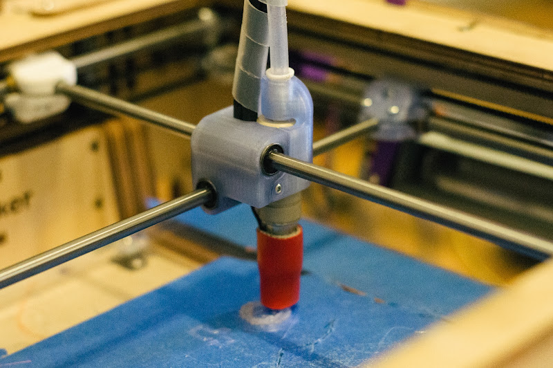
    Well, despite my previously stated enthusiasm to test out a more minimal printhead enabled by the crossflow cooling fan, I had resolved to be content with my stock(-ish) printhead and crossflow fan setup as it was, because everything was just working so well and I have d245777abca64ece2d5d7ca0d19fddb6.png+1 other projects I need to be working on instead.
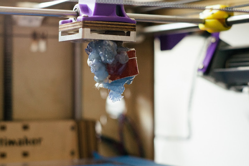
    Then, last night, during a somewhat challenging print (which I probably shouldn't have tried unattended), the print came loose from the build platform, with printer proceeding to knock it around the build chamber for 5 or 6 hours, until it "completed". At some point during that beating, it must have connected hard enough that the brass tube of the stock hotend actually cracked - because this is what I woke up to:

    DSC07313-1.jpg

    Yikes!

    Anyway, I luckily had an entirely new printhead+hotend assembly waiting to be installed - one that uses the Printrbot UBIS hotend. After doing a bit of searching, it seems to be one of the smartest, lightest hotends on the market, and looked very well suited to an ultra-minimal printhead design:

    DSC07316-2.jpg

    After setting aside some of my time today in order to make the install happen, I am excited to say that it works! And it seems to work well. I was worried that there would be thermal creep through the PEEK insulator into the PLA printhead, but after a few hours of printing at 230°, it seems to be stable. I need to do a lot more printing before giving it a more comprehensive judgement than that, but there seems to be potential here. This may be the lightest and smallest setup possible with commercially available hotends. The integrated ceramic heater enables a very small heat zone and blocks very little airflow from the crossflow fan. The pre-assembled seamless design and teflon liner should prevent any leaking or clogging. After more extensive testing, I will post more photos and all of the necessary files to replicate this setup in next few days.


  • Link to post
    Share on other sites

    Posted · The physics of cooling?

    Ouch!

    I should definitely start to build up a stock of some ready-to-use spare parts.

    This one of the most minimalistic printheads designs I've seen so far.

    After all I've heard about the all-metal hotends so far this might be an interesting alternative especially for printing PLA. However, it seems that UBIS hotends are sold exclusively via printrbot and the ceramic heater versions are hard to get. And it's hard to believe that the cartridge heater type shares the same properties (heat zone length).


  • Link to post
    Share on other sites

    Posted · The physics of cooling?

    Nick, I'd suggest that you remove some of the insulation higher up on the hot end, so that some of the cooling air can get in there and mitigate any thermal creep. You might even want to heat-sink that area.

    One of the issues I ran into with the thermal sock was that it was too effective and extended the hot zone, leading to clogs. I had to redesign the sock so that it left the area above the hot-block exposed, and that eliminated the clogs.


  • Link to post
    Share on other sites

    Posted · The physics of cooling?

    Yeah the availability of the ceramic UBIS remains an open question. They didn't have it in stock for a long time, but it seems to be back now. I also have the cartridge version and it is indeed much clunkier and probably doesn't work as well in this application.

    Regarding thermal creep, I can say that so far, it seems to be totally under control. I'm currently 13 hours into a print with a decent amount of retraction and the clamp zone of the printhead still feels to be at room temperature. I also printed the star ornament last night (basically 3 hours of constant retraction) and there was no problem with clogging. Will post more thorough review when I get more prints in.

    edit: Just completed a 25 hour print with this setup; the print head was as cool when it finished as when it started.


  • Link to post
    Share on other sites

    Posted · The physics of cooling?

    Not a true warping torture test, but once again I have to say this is the best setup I have ever used.

    sidecover.jpg


  • Link to post
    Share on other sites

    Posted · The physics of cooling?

    Someone mentioned sugru, I'm currently using a sugru "hot end warmer". I just used some vegetable oil on hotels as the release agent, the sock came off clean afterwards. Even though they say it's only stable up to 180, I've tried 260 and it's still fine. Became a bit brittle inside but still useable.

  • Link to post
    Share on other sites

    Create an account or sign in to comment

    You need to be a member in order to leave a comment

    Create an account

    Sign up for a new account in our community. It's easy!

    Register a new account

    Sign in

    Already have an account? Sign in here.

    Sign In Now

    • Our picks

      • UltiMaker Cura 5.7 stable released
        Cura 5.7 is here and it brings a handy new workflow improvement when using Thingiverse and Cura together, as well as additional capabilities for Method series printers, and a powerful way of sharing print settings using new printer-agnostic project files! Read on to find out about all of these improvements and more. 
         
          • Like
        • 18 replies
      • S-Line Firmware 8.3.0 was released Nov. 20th on the "Latest" firmware branch.
        (Sorry, was out of office when this released)

        This update is for...
        All UltiMaker S series  
        New features
         
        Temperature status. During print preparation, the temperatures of the print cores and build plate will be shown on the display. This gives a better indication of the progress and remaining wait time. Save log files in paused state. It is now possible to save the printer's log files to USB if the currently active print job is paused. Previously, the Dump logs to USB option was only enabled if the printer was in idle state. Confirm print removal via Digital Factory. If the printer is connected to the Digital Factory, it is now possible to confirm the removal of a previous print job via the Digital Factory interface. This is useful in situations where the build plate is clear, but the operator forgot to select Confirm removal on the printer’s display. Visit this page for more information about this feature.
          • Like
        • 0 replies
    ×
    ×
    • Create New...