
Good point - don't think it's Z thread related as there is no 3mmi-ish periodic pattern to the banding.

Good point - don't think it's Z thread related as there is no 3mmi-ish periodic pattern to the banding.
Good point - don't think it's Z thread related as there is no 3mmi-ish periodic pattern to the banding.
Hi,
are you willing to share the stl file of your solid somewhere?
Than we can experiment with the same file....
I had a lot of success with adding more weight to the z-stage,
and a bowden dampener is something I will also try 
and please share the file, so we can do a comparison print
also printing with an opaque color will also show more detail.

I'm looking forward to these comparisons... it would be especially nice to know what kind of filament was used (material (e.g. PLA vs. PLA/PHA), origin of the material, measured filament thickness).
Uncoupling the extruder from the frame might be a good idea to reduce vibrations...maybe this is a major difference between UM1 and UM2?
Filament was Ultimachine White PLA, though I'm out of that filament now, and will resume testing in Printbl White PLA. Which will also be a good time to test the possibility that filament variation is one culprit. Will probably do that tomorrow.
Uncoupling the extruder from the frame might be a good idea to reduce vibrations...maybe this is a major difference between UM1 and UM2?
You could use the mounting aid I designed for dual-extrusion to create more damping between the frame and the feeder: https://www.youmagine.com/designs/dual-extrusion-mounting-aid
But I do not think that can be the cause. I have seen this happen with varying thickness of filament, as well as with slipping filament on the feeder, by too much OR too little pressure on the spring.
I like Daid's theory - slipping on the extruder. You could print at 1/5 the speed and see if that helps.
My theory is Z axis movement. It sticks a little or something and when you command it to go down .1mm it actually goes down .07mm and so you get 30% over extrusion and the layer sticks out. Then you command another .1mm and it corrects and goes down .13mm and you get 30% under extrusion. Something like that.
Tried another rounds of tests this evening. After watching the machine print for a while, I felt the theory of uneven Z steps causing uneven extrusion seemed likely. I ran 4 more of the same prints while tweaking some settings, and there were some further improvements made. Everything was the same as the previous set, except I was using Ultimachine Yellow PLA instead of Ultimachine White. All tests included the dampening weight on the bowden which showed improvement last time.
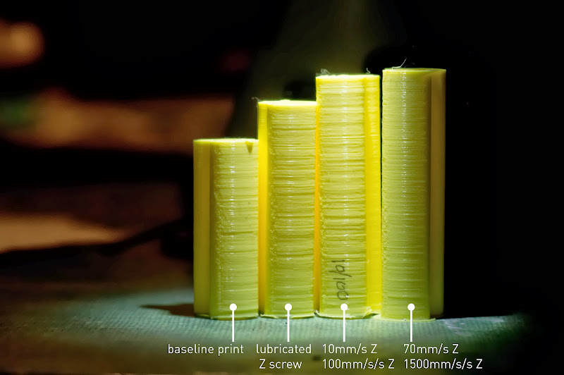
The first change I made was lubricating the Z lead screw with a high quality teflon + lithium grease made for helical gears. This did not seem to make much of a change in print quality (maybe a slight improvement?) apart from making my Z moves quieter.
Second change was lowering the speed and acceleration of Z moves in firmware. I dropped the Z velocity from 40 to 10mm/s, and the acceleration from 700mm/s/s to 100mm/s/s. This noticeably decreased print quality - there was definitely more banding.
With that knowledge, I increased the Z values up to 70mm/s and 1500mm/s/s (important note: prior to re-greasing my lead screw, the machine could not handle these values without skipping steps). This definitely increased quality beyond the starting print.
Conclusions so far:
- Dampening the bowden reduces banding
- Increasing Z velocity and acceleration reduces banding
- Having the Z lead screw well lubricated is required in order to have successful fast Z moves.
I think the next set of tests will revolve around varying the tension of the extruder spring, as suggested by Daid.
Actually, it seems that I'm still getting some skipped steps when using 1500mm/s/s Z acceleration. I turned it down to 900, seems ok, but I may need to tweak my Z stepper driver to give more current.
Interesting to see that high acceleration seems to give more even results. Any theory as to why that should be?
Btw, looking at the math for the acceleration planning, I think you can pretty much ignore changing the move speeds much. For a 0.15mm layer, even with acceleration at 1500mm/s², the top planned speed for the move is going to be about 15mm/s. The fact that it's potentially allowed to go faster is moot, because there isn't any time to get up to a higher speed before it's time to slow down again. Speed is going to be limited by distance and acceleration rate, more than any cap on the speed itself, for all practical purposes (provided your max z speed isn't in the single digit range).
Useful to know, and actually very relevant to my last post. I'm not getting skipped steps during the incremental layer changes - I'm getting skipped steps during the initial bed lowering routine that Cura performs. An ideal setup might then be 1500+mm/s/s acceleration but 15mm/s or so max velocity - maximizing layer change efficiency but preventing crazy speeds during initial bed lowering.
Just tested this and yes, keeping velocity low with acceleration high is absolutely the way to go. Z velocity is set to 16mm/s and Z acceleration is set to 1500mm/s/s - and now the initial bed lowering happens nice and slowly, but the inter-layer z changes are still a lightning fast chirp. More testing is probably warranted here to find the best balance of these two values.
You can always just set the f-speed of the moves appropriately in the start and end gcode, too. :-)
Oh. Yup. See that now. That works too.
Some days ago I had a closer look to http://umforum.ultimaker.com/index.php?/topic/3695-acceleration-in-marlin/ with some very helpful contribution from Daid and gr5.
I wonder what influence the z-jerk could have on these lines (has the z-jerk actually the same meaning in z as the xy-jerk in x/y?)
Yes, it means the same thing. The z-jerk setting is already very low by default - 0.4mm/s. Don't know if you've seen my http://www.extrudable.me/2013/04/02/the-myth-of-z-speed/; I didn't pay much attention to z-jerk, but I did talk about speed and acceleration as it relates to z.
Yes, it means the same thing. The z-jerk setting is already very low by default - 0.4mm/s. Don't know if you've seen my blog post on z-speed; I didn't pay much attention to z-jerk, but I did talk about speed and acceleration as it relates to z.
I had it actually marked for reading a few days ago... :wink:
After heaving read it now: Has someone played around with z-jerk in the meantime? Obviously to put it to something like 30mm/s is not a good idea. Where is the threshold where slipping at the beginning of the movement starts?
It might be worth a try after Nick's findings with the higher z speed and acceleration.
Interesting to see that high acceleration seems to give more even results. Any theory as to why that should be?
[...]
A very good question. If we would transform the transient movement into a power spectrum (by Fourier transform), we would get more amplitude at higher frequencies for the faster movement due to the steeper slopes. Attenuation might be higher for higher frequencies. However, I would expect this effect to be small except we are in resonance somewhere...

Just my two cents.
At the beginning of every z-step there is a breakaway torque between z-screw and nut to overcome. Slow acceleration would increase the time until breakaway torque is reached and - within that time - transfer unwanted movement to the nut, causing some displacement in x/y/z. Fast acceleration will overcome the breakaway torque almost instantly and therefore transfer less unwanted movement to the nut / print bed.
A very interesting thought!
Brings us back to the question if the pattern is the result of a displacement or a thickness variation...
My UM1 is behaving quite well at the moment concerning these wobbles. I'm using 10mm/s and 1500mm/s^2 for the z axis. I also find the wobbles much smaller at 0.06mm layer height compared to 0.1mm.
Just another 2 cents...
I normally run kisslicer with 0.5mm z lift on retractions, with the Z acceleration set high (900mm/s/s from memory). This snaps up and down so fast in the retraction you can hardly see it move.
I tried a job last week with the latest Cura, because it wasn't slicing well with kiss, and I couldn't find any z lift feature, so went without it.
The banding was much, much worse.
This to me supports the theory that there is a stiction and breakaway factor in the Z nut as the z lift would remove that.
I wonder what influence the z-jerk could have on these lines (has the z-jerk actually the same meaning in z as the xy-jerk in x/y?)
Pretty much. jerk mostly affects when you are moving in the same axis two line segments in a row. It allows the axis in motion not to have to come to a complete stop at the end of each segment.
Since there aren't normally two z moves consecutively, max z jerk is less of a factor. But basically it sets the initial speed before acceleration and the final speed at the end of deceleration. In other words instead of smoothly accelerating from speed 0, it starts at speed max_z_jerk (and I think ends at either max jerk or max_jerk/2).
The code is a bit confusing - I just spent an hour looking at it again (planner.cpp). A great effort was made to document and explain it. And it is much easier to read code than most code I've read in my lifetime. But it's still quite confusing.
Keep in mind, jerk in Marlin is not the normal physics definition of jerk - it's more closely defined as the maximum instantaneous velocity change allowed at a vertex. It's in mm/sec. It's a velocity.
So, yes. Changing max z jerk will make a difference.
Some time ago I found that my x and y rods could slip along there axis (one of them by about 2mm). Today I finally fixed this with an adjustable end cap (http://www.thingiverse.com/thing:54075). The play is now something like one or two tenth.
And I found the 'z wobble' became much smaller! So it's maybe a good thing to check the rods in order to give the vibrations no chance to produce a displacement.
I'll have a look if I find some 'before-after'-pictures...

ArunC posted a topic in UltiMaker Cura,

.thumb.jpeg.0b7a05eafc09add17b8338efde5852e9.jpeg)
Dustin posted a topic in Firmware,


Recommended Posts
Dim3nsioneer 557
Very nice analysis, Nick!
I've been doing tests as well in order to get rid of the remaining wobbles. My analysis showed that some of them are rather caused by a variation of the z step or a variation of the flow (due to the last remaining imperfections of otherwise high-quality filament).
Other wobbles are actually not a variation in print thickness but x/y-shifts which might rather be caused by the z thread and the bed itself (and vibrations of course).
Which type are your remaining print imperfections of? It's not quite visible from the pictures which are otherwise great.
Link to post
Share on other sites