Jump to content

The crossflow fan approach


Recommended Posts

Posted · The crossflow fan approach

Typically, a fan can draw much more current at startup than specified for running at full speed. Maybe that's what happened. Did you try to run the fan with PWM? Typically, fans from ebmpapst St. Georgen are not specified to run with a PWM 24VDC (means they could produce some spikes?). They have seperate models with a PWM signal line.


  • Link to post
    Share on other sites

    • Replies 142
    • Created
    • Last Reply

    Top Posters In This Topic

    Posted · The crossflow fan approach

    The crossflow fan has just two cables (+\-) and no pwn control. When I had the transistor dead was after a minute or so testing speeds with the ulticontroll. The crossflow starter at 40-60/255 and at 255 it literally could make the filament fly.

  • Link to post
    Share on other sites

    Posted · The crossflow fan approach

    Typically, a fan can draw much more current at startup than specified for running at full speed. Maybe that's what happened. Did you try to run the fan with PWM? Typically, fans from ebmpapst St. Georgen are not specified to run with a PWM 24VDC (means they could produce some spikes?). They have seperate models with a PWM signal line.


    If it is not designed for PWM, could their be problems from the inductive load causing voltage spikes?


  • Link to post
    Share on other sites

    Posted · The crossflow fan approach

    This fan still draws around 10 times as much current as a usual fan - That means much higher inductive load and higher voltage spikes on PWM control. NPN transistor? Not a good idea...

    You could try flattening out that PWM by adding an RC lowpass filter / tank after the PWM output stage. It might take some tinkering with different values, but it's possible to come pretty close to a regulated DC voltage with that trick.

    I'll try it out myself once I get to install my crossflow fan. But there's too much other stuff to tend to atm :(


  • Link to post
    Share on other sites

    Posted · The crossflow fan approach

    You could try flattening out that PWM by adding an RC lowpass filter / tank after the PWM output stage. It might take some tinkering with different values, but it's possible to come pretty close to a regulated DC voltage with that trick.

    I'll try it out myself once I get to install my crossflow fan. But there's too much other stuff to tend to atm :(


    I had pretty good luck putting an RC filter on a normal fan. PWM is 30khz, which seems high enough to easily filter.

  • Link to post
    Share on other sites

    Posted · The crossflow fan approach

    Anyone knows if something like this could work connecting this between the crossflow fan and the board direct 24v output to the fan? http://www.aliexpress.com/item/6V-30V-6A-Reversible-DC-Motor-Speed-Control-PWM-Controller-Switch-PWM-Regulation-Fan-Control-for/32221565091.html


    It could work - as long as you don't put the control switch to reverse mode. That will probably damage the fan. And you can't control it through the UMO fan output anymore because most control inputs of such drivers won't allow 19V input.


  • Link to post
    Share on other sites

    Posted (edited) · The crossflow fan approach

    Well today arrived the item, (didn't bough that one because of that 'reverse' option).

    $_1.JPG

    Got this one, and connected it to the 19-24V output (the 2 pin near the start of the board) and it works like a charm. I forgot how noisy it's the fan. Anyhow it works, I just need to finish my dual extruder magnet stuff and I'll get my hands on a good 3d printed support for this model & casing for this external PWM.

    Edited by Guest
  • Link to post
    Share on other sites

    Posted · The crossflow fan approach

    After lurking for a long time I just installed a 200 mm. cross flow fan in my UMO and finished my first PLA print.

    I dont even have the sides closed off yet, but am already in love with the setup... super slick and works a treat...

  • Link to post
    Share on other sites

    Posted (edited) · The crossflow fan approach

    I made an adjustable mount for the papst QG030 series fans. It is a little rough and heavy handed, but seems functional.

    https://www.youmagine.com/designs/umo-papst-crossflow-adjustable-mount

    o9WlkJNm.jpg

    Edited by Guest
  • Link to post
    Share on other sites

    Posted · The crossflow fan approach

    @Aaron

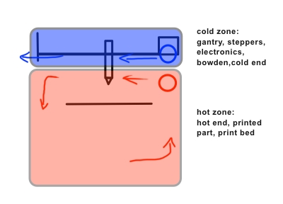
    Exactly! If I would have to design a printer I would start with your idea. It's the most straightforward approach to provide an optimum thermal situation.

    printer-schematics.jpg

    Has anyone rotated their printer 180 degrees so the device is upside down?  I can see a few problems with this like bridging creating hanging bits that would hit the printer head.  I ask because in some regards I think this would be the easiest way to retain the heat in the printer in the correct areas of the printer.  Keeping cool air at the "bottom" of the printer separated from the hot air at the "top" as a function of the differences in their densities.  Probably not worth the hassle though, but an interesting thought.

    Anyone tried this yet? I had originally bought a fan off e-bay that didn't work at first, so I ordered another. I just got the first fan working again, so now I have two mostly identical crossflow fans.

  • Link to post
    Share on other sites

    Posted · The crossflow fan approach

    AFAIK no one tried this yet. But it would be tempting particularly for actively cooled hotends to get rid of the tiny fans.

  • Link to post
    Share on other sites

    Posted · The crossflow fan approach


    @Aaron

    Exactly! If I would have to design a printer I would start with your idea. It's the most straightforward approach to provide an optimum thermal situation.

    printer-schematics.jpg


    Has anyone rotated their printer 180 degrees so the device is upside down?  I can see a few problems with this like bridging creating hanging bits that would hit the printer head.  I ask because in some regards I think this would be the easiest way to retain the heat in the printer in the correct areas of the printer.  Keeping cool air at the "bottom" of the printer separated from the hot air at the "top" as a function of the differences in their densities.  Probably not worth the hassle though, but an interesting thought.


    Anyone tried this yet? I had originally bought a fan off e-bay that didn't work at first, so I ordered another. I just got the first fan working again, so now I have two mostly identical crossflow fans.


    So that's two crossflow fans? Seems a little overkill (and expensive too...)...

    How would it work in terms of turbulence (where does the air go after cooling the hotend)?

    I played around with the idea of using just my single crossflow fan to also cool my E3D hotend, but then realized that this would only work for the prints where you actually want the print cooled... All the time... A fan that slowly starts up over the first few layers would be no good...

    Two fans would solve this, but I am concerned with all the excess cold air... Would you have an opening in the printer on the other side for air to escape?

  • Link to post
    Share on other sites

    Posted · The crossflow fan approach

    There does not seem to be a turbulence problem between the two fans. The air for cooling the hot end would be directed into the room. The point of using two is that the top fan can draw cool air from the room, while the bottom fan recirculates air around the heated bed.

    I am not sure if it matters if the top and bottom fans are running at different speeds.

  • Link to post
    Share on other sites

    Posted (edited) · The crossflow fan approach

    After lurking for a long time I just installed a 200 mm. cross flow fan in my UMO and finished my first PLA print.

    I dont even have the sides closed off yet, but am already in love with the setup... super slick and works a treat...


    Which fan did you use, tommyph1208, and what modifications to the UMO electronics did you do, if any? I was getting ready to get a QG030-198/12 for my UMO, but the exchange between jonnybischof and neotko has me wondering if I'm out of my depth on the electronics. The QG030-198/12 could draw ~670mA with the fan at 255. The fan that came with my UMO looks to be rated at 100mA. I see how everyone is suggesting running at no greater than 40-50%, but I'd hate to be one forgotten profile setting away from blowing the main board.

    Edited by Guest
  • Link to post
    Share on other sites

    Posted · The crossflow fan approach

    Which fan did you use, tommyph1208, and what modifications to the UMO electronics did you do, if any? I was getting ready to get a QG030-198/12 for my UMO, but the exchange between jonnybischof and neotko has me wondering if I'm out of my depth on the electronics. The QG030-198/12 could draw ~670mA with the fan at 255. The fan that came with my UMO looks to be rated at 100mA. I see how everyone is suggesting running at no greater than 40-50%, but I'd hate to be one forgotten profile setting away from blowing the main board.


    I do not know the brand (or even how much current it draws at full speed), I bought it off a Danish shop that deals in car audio systems... Apparently if you are a really cool guy, you have amplifiers in your car, so big that they require a fan like this to keep cool :/

    Anyways, I run my printer at 24V off a RUMBA board (fan is still 12V though)

  • Link to post
    Share on other sites

    Posted · The crossflow fan approach

    I do not know the brand (or even how much current it draws at full speed), I bought it off a Danish shop that deals in car audio systems... Apparently if you are a really cool guy, you have amplifiers in your car, so big that they require a fan like this to keep cool :/

    Anyways, I run my printer at 24V off a RUMBA board (fan is still 12V though)


    I keep running into those car system fans as well, but I can't find any with impellers ~200mm that pull suitable mA.

    I guess there is no reprieve from the 1.5.7 board fan power constraints unless I add external power, or bite the bullet and replace the stock board (I have been eyeing the Smoothieboard 5x for another build).

  • Link to post
    Share on other sites

    Posted · The crossflow fan approach

    I keep running into those car system fans as well, but I can't find any with impellers ~200mm that pull suitable mA.

    I guess there is no reprieve from the 1.5.7 board fan power constraints unless I add external power, or bite the bullet and replace the stock board (I have been eyeing the Smoothieboard 5x for another build).


    Yeah, I needed more power for a heated bed as well, and so in the end I found it easiest to simply swap everything... I don't regret it either, RUMBA has been super nice, lots of possibilities, little restraints.

    I always found the large laptop psu next to the printer kind of fail considering the amount of space available underneath the printer, but I guess price was a factor for ultimaker here... I raised the printer a few cm. with some printed feet and mounted a 300W 24V industrial PSU down there to pull everything... As an added bonus it vents hot air into the build area through some holes I cut in the bottom cover ;)

  • Link to post
    Share on other sites

    Create an account or sign in to comment

    You need to be a member in order to leave a comment

    Create an account

    Sign up for a new account in our community. It's easy!

    Register a new account

    Sign in

    Already have an account? Sign in here.

    Sign In Now

    • Our picks

      • UltiMaker Cura 5.7 stable released
        Cura 5.7 is here and it brings a handy new workflow improvement when using Thingiverse and Cura together, as well as additional capabilities for Method series printers, and a powerful way of sharing print settings using new printer-agnostic project files! Read on to find out about all of these improvements and more. 
         
          • Like
        • 18 replies
      • S-Line Firmware 8.3.0 was released Nov. 20th on the "Latest" firmware branch.
        (Sorry, was out of office when this released)

        This update is for...
        All UltiMaker S series  
        New features
         
        Temperature status. During print preparation, the temperatures of the print cores and build plate will be shown on the display. This gives a better indication of the progress and remaining wait time. Save log files in paused state. It is now possible to save the printer's log files to USB if the currently active print job is paused. Previously, the Dump logs to USB option was only enabled if the printer was in idle state. Confirm print removal via Digital Factory. If the printer is connected to the Digital Factory, it is now possible to confirm the removal of a previous print job via the Digital Factory interface. This is useful in situations where the build plate is clear, but the operator forgot to select Confirm removal on the printer’s display. Visit this page for more information about this feature.
          • Like
        • 0 replies
    ×
    ×
    • Create New...