


GregValiant 1,246
I think if the "squareness" of the printer is off it won't be by much or your previous parts would have shown an indication.
Regarding the temperatures - Are you confident in the sending units/thermistors calibration? Is it possible they aren't just measuring the device they are supposed to monitor but picking up some residual heat from another source (like the bed isn't that hot but the thermistor is affected by another device?)
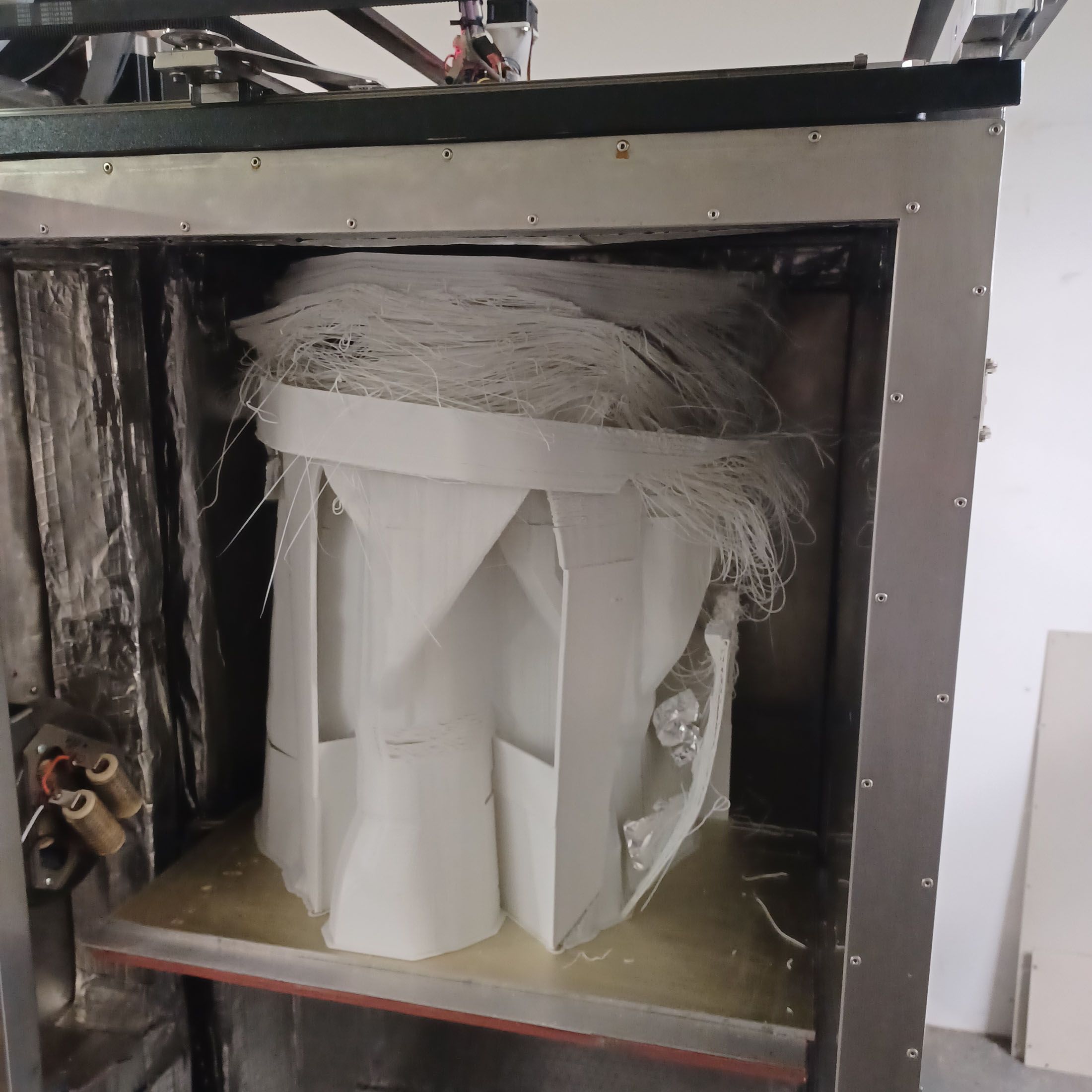
When you get a minute, step back and take an overall picture of the whole gizmo. The biggest that's been posted here is this one I named Godzilla. It uses a big ole pellet-fed extruder. He was doing flat panels and wanted to print them in Vase Mode. I helped a bit in redesigning the parts so it could be done.


.thumb.jpeg.0b7a05eafc09add17b8338efde5852e9.jpeg)
Recommended Posts
coseng 4
Thanks! There's still more speed to come, but for now I need to print some parts and not bother about pushing the limit.
Have a few good runs under my belt and am feeling pretty good about the settings. I revised the layer duct fan to blow a bit more and reduced the minimum layer time to 15 sec with no apparent change in the good results.
Still not quite sure I understand the thermal relationships going on. It takes setting the chamber temp to 35C for the bed heater to actually cycle. At 40C chamber or above it reads a couple of degrees over the setpoint of 90C, and continually reads 92 or 93.
Wondering if in the duet 6hc or rrf firmware if there some way to log or graph the activity of all the heater circuits to see what their duty cycles are. Maybe the good insulation and almost 80W of heat input from the printhead is enough to keep the chamber up to temp, as unlikely as that seems. At 50C chamber temp the outside surfaces are warm to the touch and the glass window pretty warm. At 35C chamber temp the outside surfaces or door window do not even feel warm.
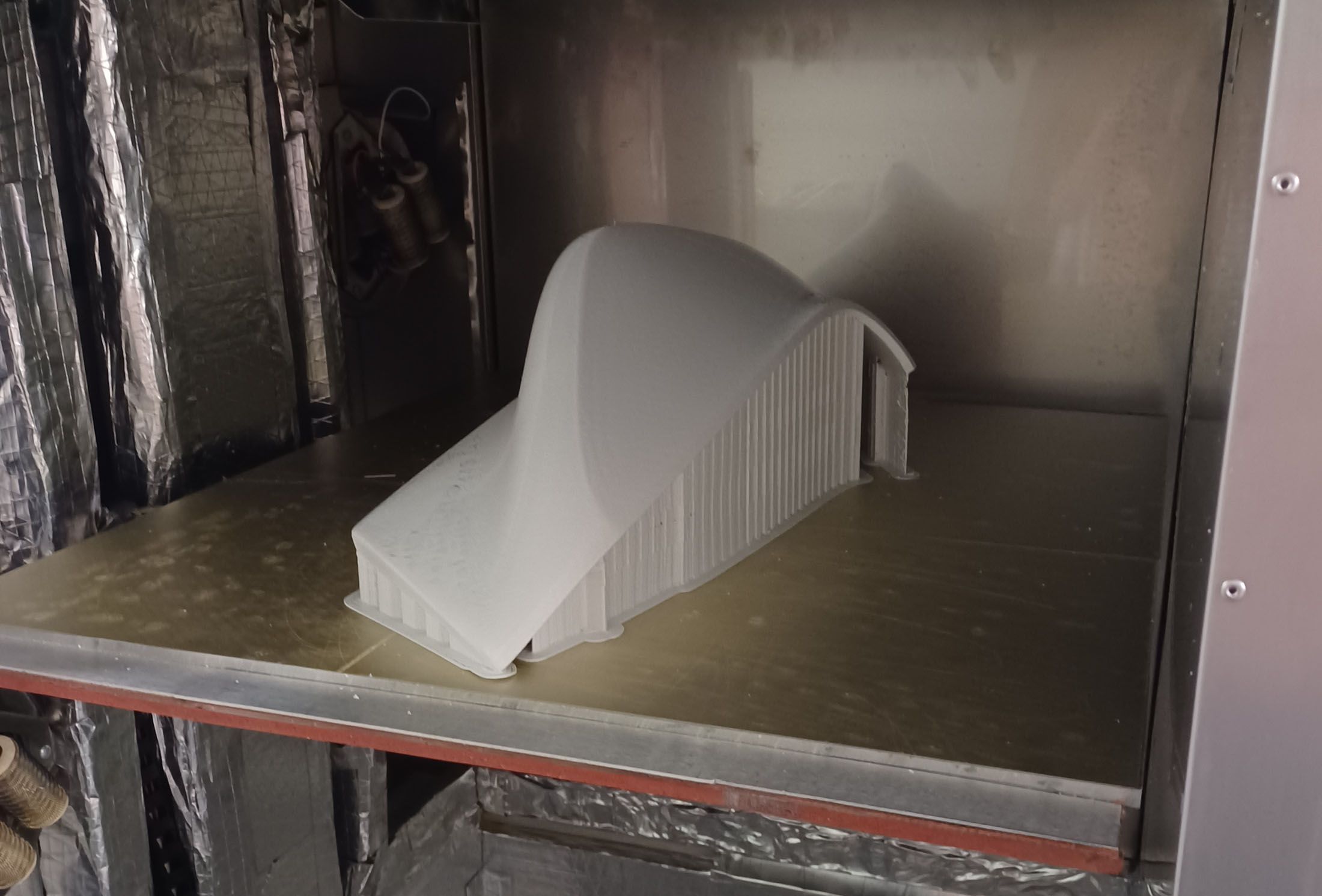
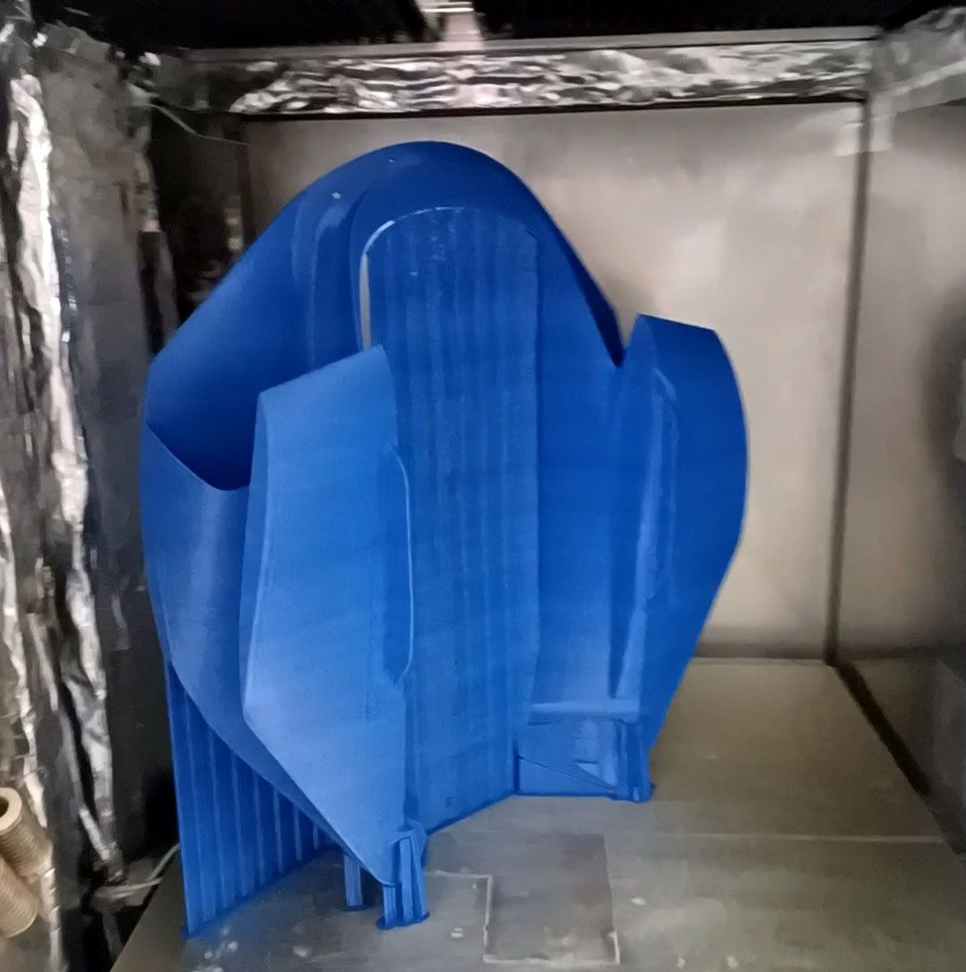
The step in the airbox part is because it was being run with no supports even with completely horizontal overhangs to see how bad the bridging was. A blob developed at one overhang and hit the nozzle and shifted the bed a little but it kept printing. I only wanted the first couple of inches anyway to check the assembly, since that is where everything mounts to.
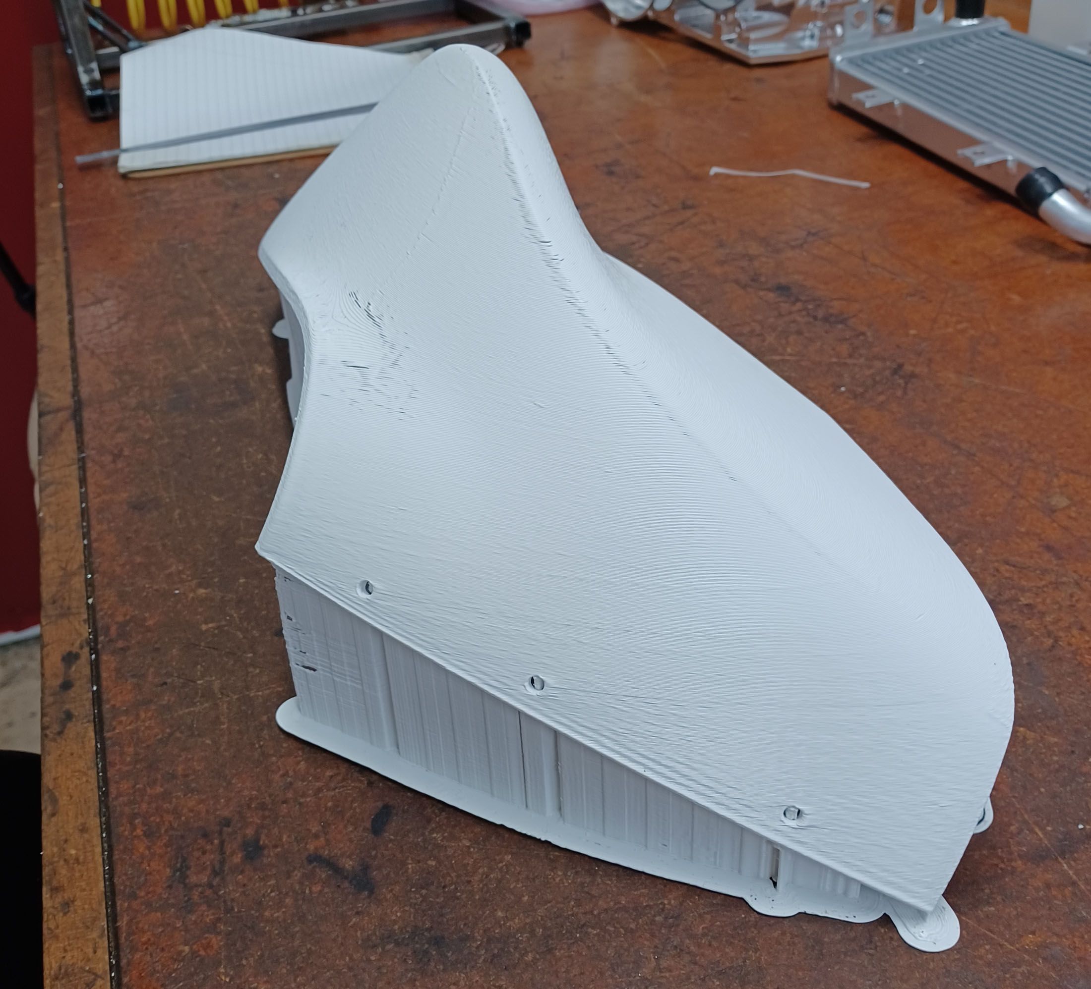
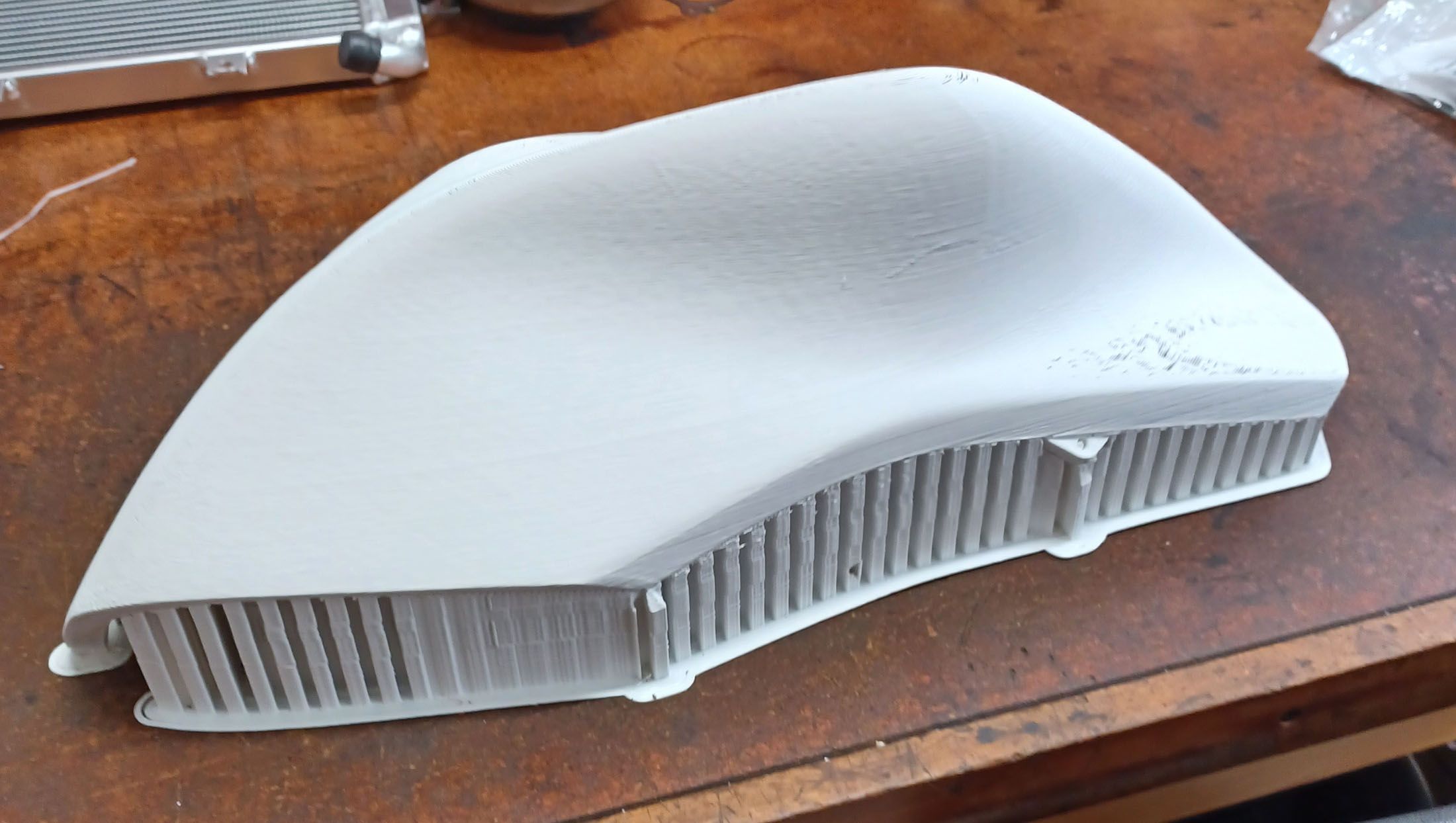
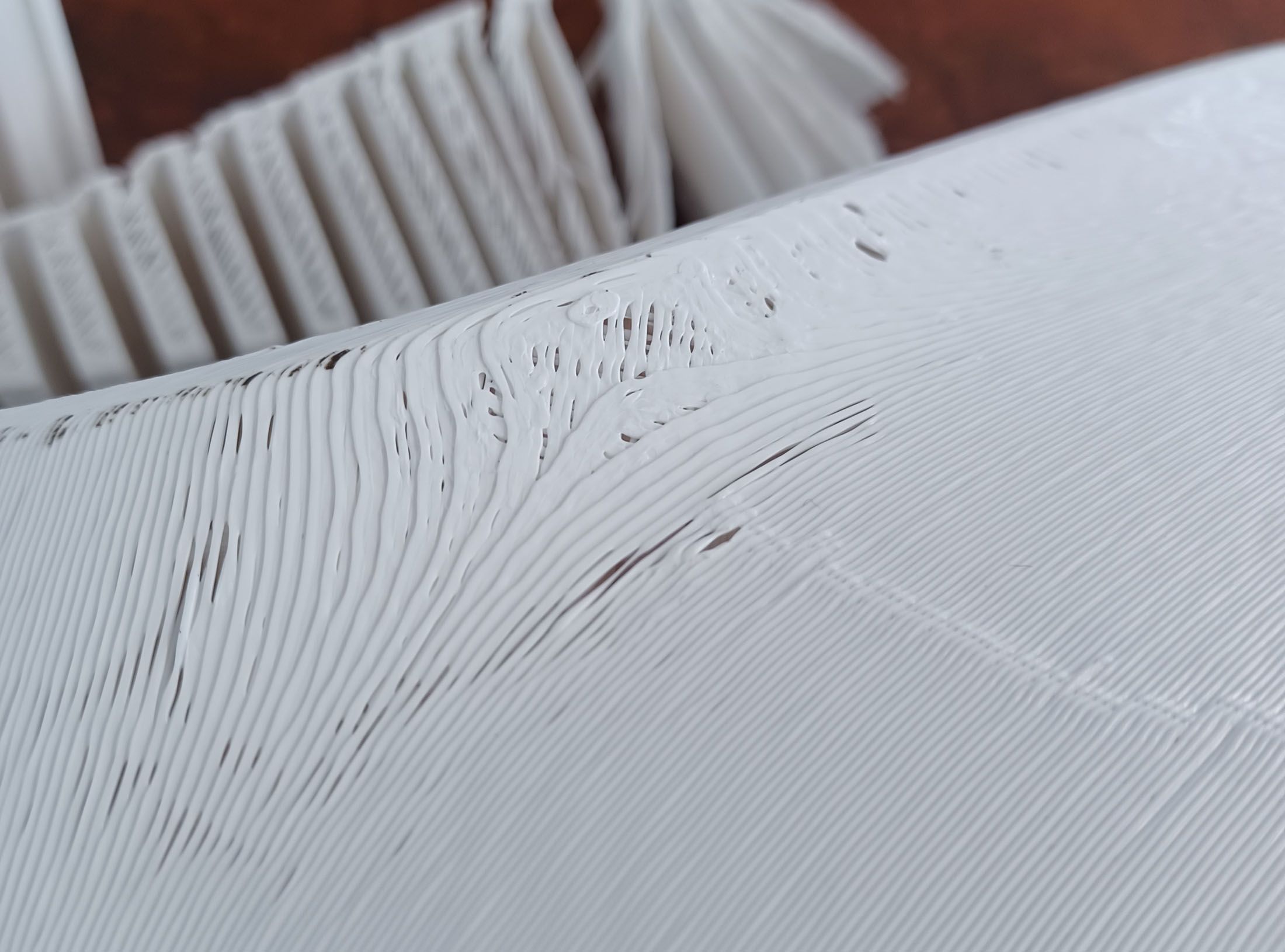
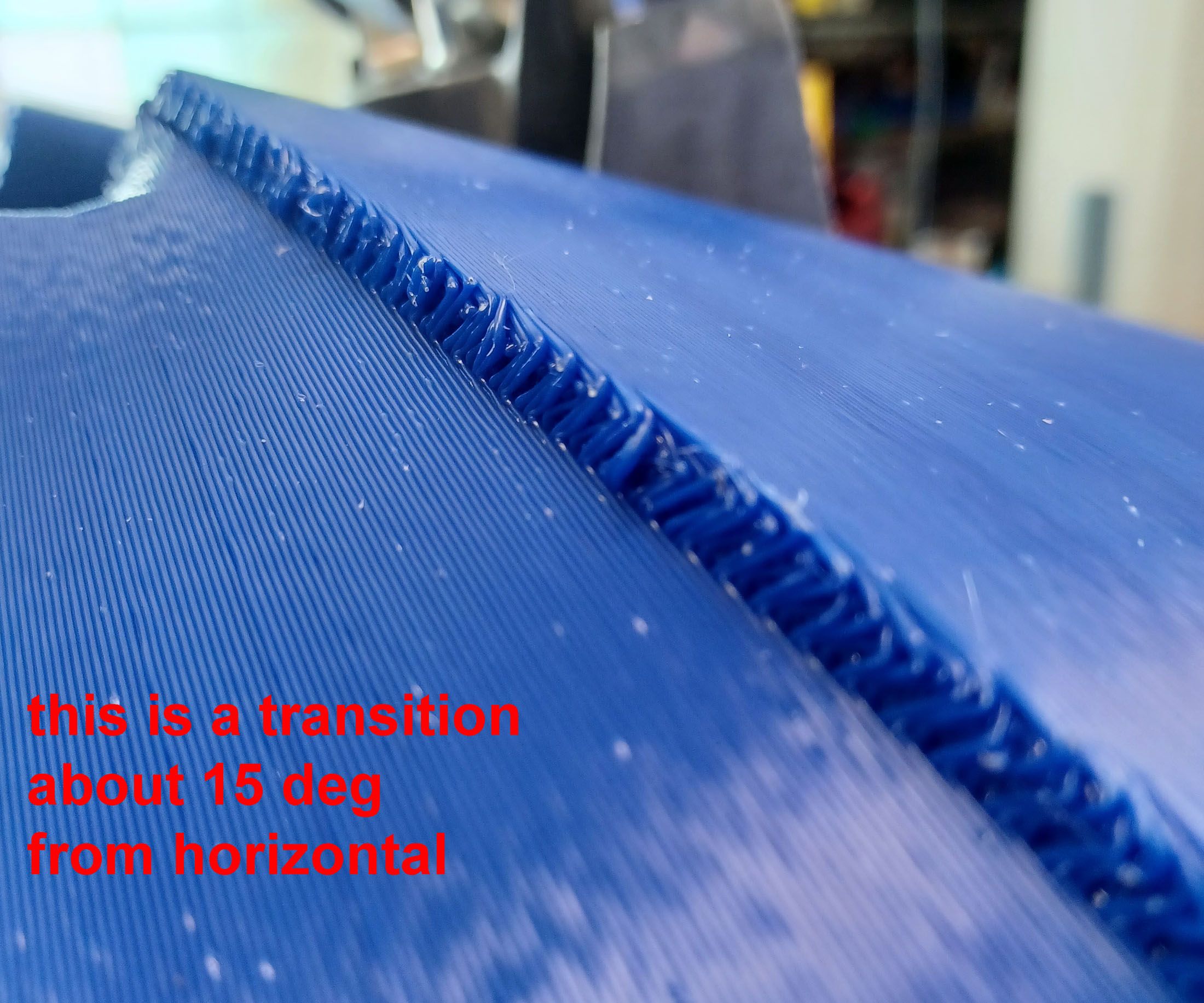
The marks on the back of the fairing parts are where I trimmed the ribs off but did not do a full finishing job. I'm very happy with the surface finish of the appearance surfaces. They have a consistent satiny appearance.
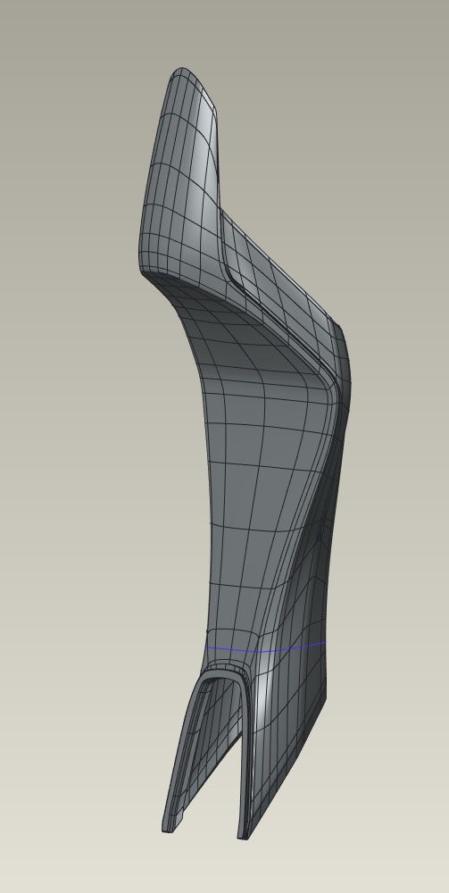
Now that I am feeling confident, one half of the gas tank/airbox cover is printing. Multiple smooth curvatures, some near vertical, some near horizontal. So far, so good. Projected to be a 13hr print and about halfway through. This is the first part with supports. I used the normal style as the tree support option resulted in a 2hr longer print time. Maybe I didn't tweak the settings optimally.
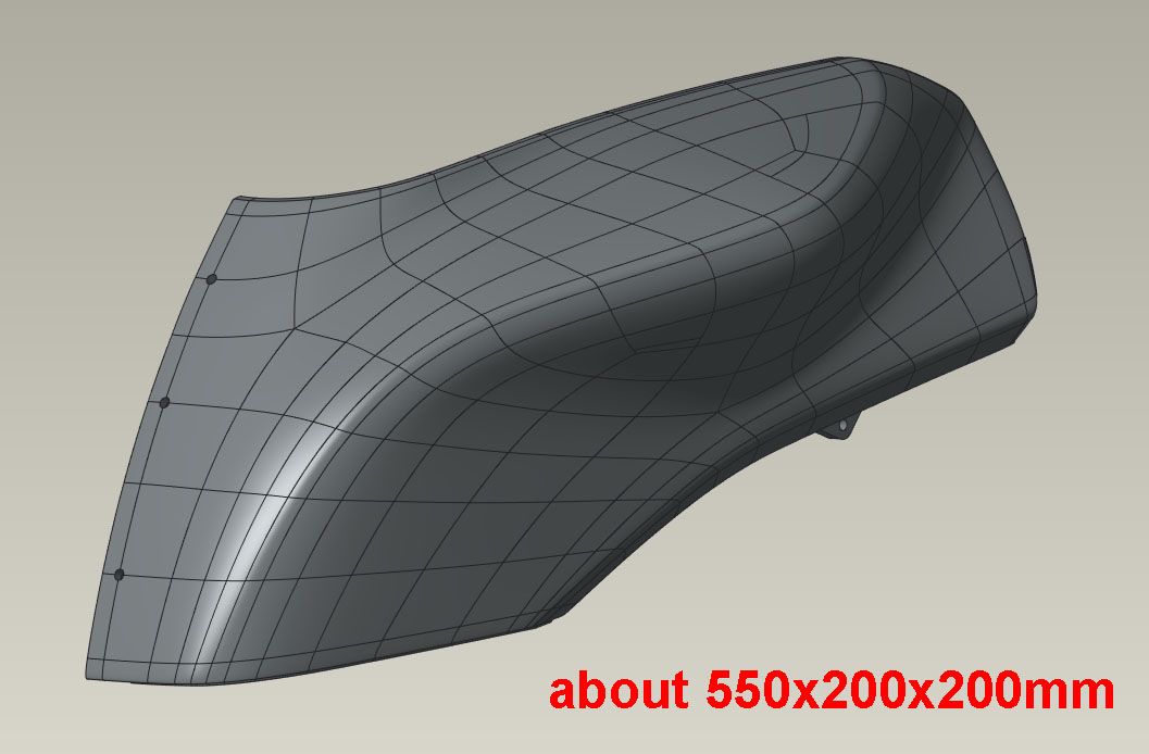
If that goes well, next I'll do the tailsection standing up, which is about 780mm tall, and really see how good the Z alignment, straightness, parallelism, etc are. I could print a large spiral vase box or cylinder and see quickly but that would be too easy!
Chris
Cosentino Engineering
Link to post
Share on other sites