
They don't let me wear my cape on the racetrack. 😞

Win a few, lose a few.
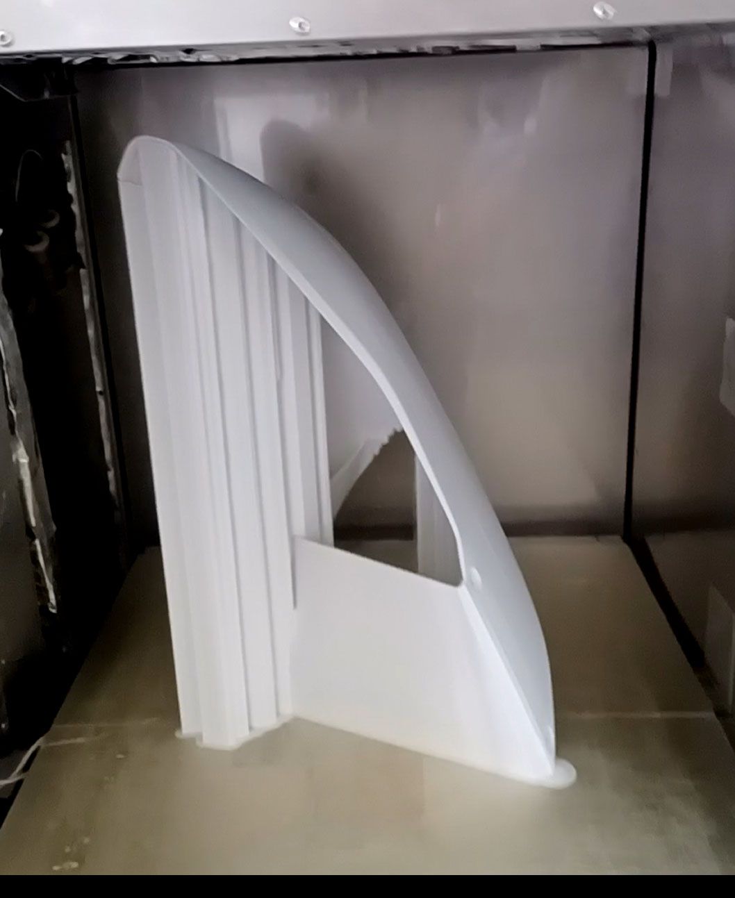
I tried running a thinnish part standing up with minimal slicer supports but thought decent CAD bracing and got an area with a failure similar to the initial thin part print failures where the end got all wiggly.

I also had an issue with the one of the chamber heaters blowing on the part and causing some sagging and warping. I tried to heat and bend it back, but it was not working good enough to make it a usable part, so back to the printer.
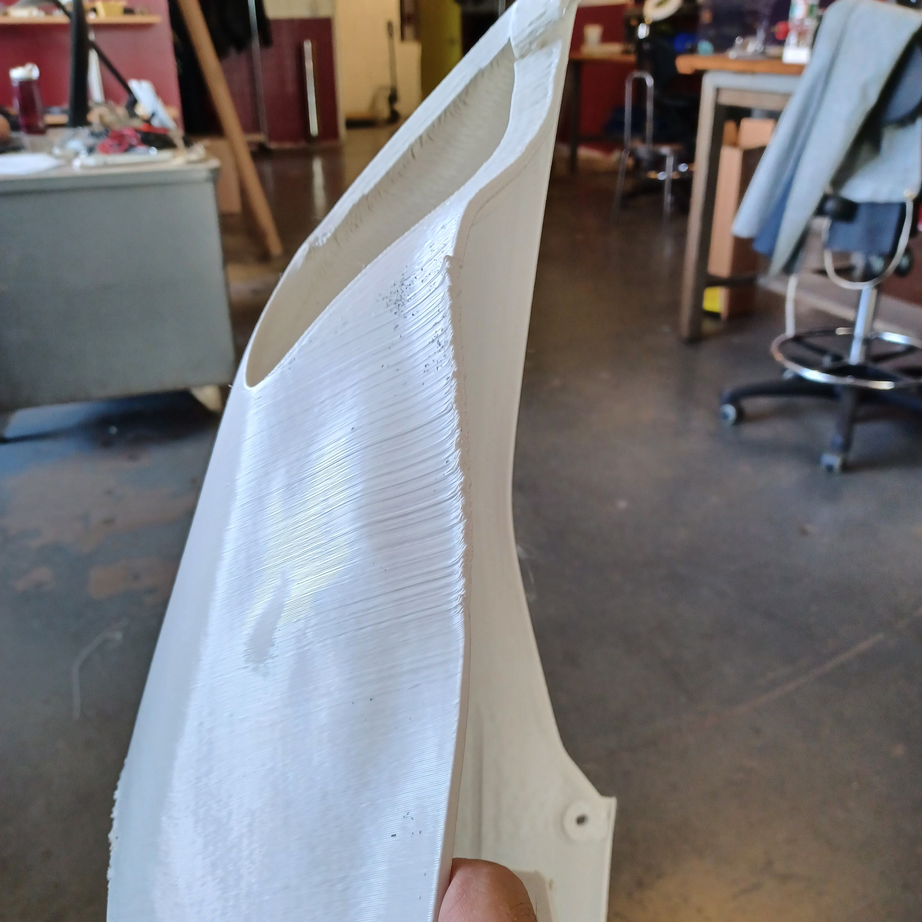
I had run this part previously laying down and got a bunch of bad finish areas on the inside under the support structure, but the other areas ran fine. With this print I made a CAD error on the wall thickness so some of the part has one pass for each wall and a small hollow space in between. The result is quite flimsy, otherwise I would have used it. I could imagine 130mph wind blowing a hole through it.

For the next print I will go back to the laydown orientation and tweak the support roof settings a little.
Happy 4th of July everybody.
Those laydown prints of the front upper sides worked well. Here's a pic of the nearly finished product. All the red, white, and blue body panels were printed out. And the black seat 'pads'.

I'm going to keep refining the slicer settings and printing more parts as I make updates to the design, but for now can consider this a completely successful printer build project.
Thanks to the forum for all the suggestions.

It looks likes it's going 150mph just sitting there. Instead of the Bat Bike I should have posted Captain America's bike (and I'm not talking about Peter Fonda).
Congratulations on the printing and on the build. I know it was a lot of head scratching as well as a lot of physical effort.
What engine will you be racing with?
Thanks!
>>What engine will you be racing with?
The engine is a semi-custom 600cc single cylinder engine using a Ducati Panigale 1199R cylinder head and piston with custom billet crankshaft, counterbalancer, and crankcases.

The frame is also unique in not using telescopic forks but a linkage system.

It looks like some of your parts are suffering from "not enough fan". What material are you printing?
4 hours ago, gr5 said:It looks like some of your parts are suffering from "not enough fan". What material are you printing?
The parts are in ABS. That style error happened a lot initially, but now only happens on thin corners of unsupported downward facing surfaces, so think I am just asking too much from the print technique.
A thumper. You're going racing with a thumper. This just keeps getting better.
I think the only thing that could make it cooler would be if it were a 2-cycle. That would be totally BA.
1 hour ago, GregValiant said:A thumper. You're going racing with a thumper. This just keeps getting better.
I think the only thing that could make it cooler would be if it were a 2-cycle. That would be totally BA.
YES!!!!!!! I love the light weight and simplicity. Well, the last bike was a lot simpler.......
I raced a RS125 GP 2 stroke for a bunch of years and that is what got me hooked on lightweight bikes.
In the search for a little more print speed (I'm a racer for a reason.....) I did a little beta testing for the people making the print nozzle with a PCD insert tip, ChampionX.
https://www.championx.com/products-and-solutions/drilling-technologies/diamondback-nozzles/
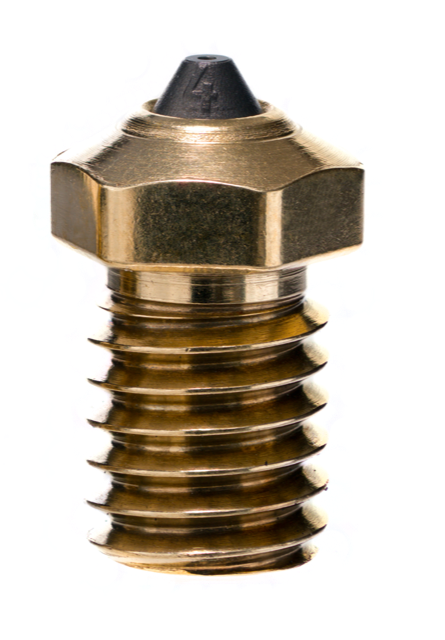
It is not a coating, but a little chunk of industrial PCD that is inserted in the tip. It is hard as a natural diamond, but black. It also has a very high thermal conductivity, so will keep the filament as hot as possible right up to the nozzle exit. That is secondary though, as diamond's low friction properties for me are the main point of interest to reduce the effort needed to push melted filament out of the orifice. Less friction leaves more stepper torque available to put to use pushing filament out, which results in higher print speeds.
The company advertises the nozzle as resistant to abrasion with CF or glass filled or otherwise abrasive filaments. I did not test any of that, but considering it is diamond, would think it would last for a printer's life. They also mirror polish the flat tip so that the tops of prints come out really smooth. The visible parts of my prints are mostly the sides of the extrusion, so also did not test this aspect.
They have products for a bunch of nozzles and are coming out with a Volcano version, but not yet for a Supervolcano, so a bit of lathe work was needed to do a retrofit.
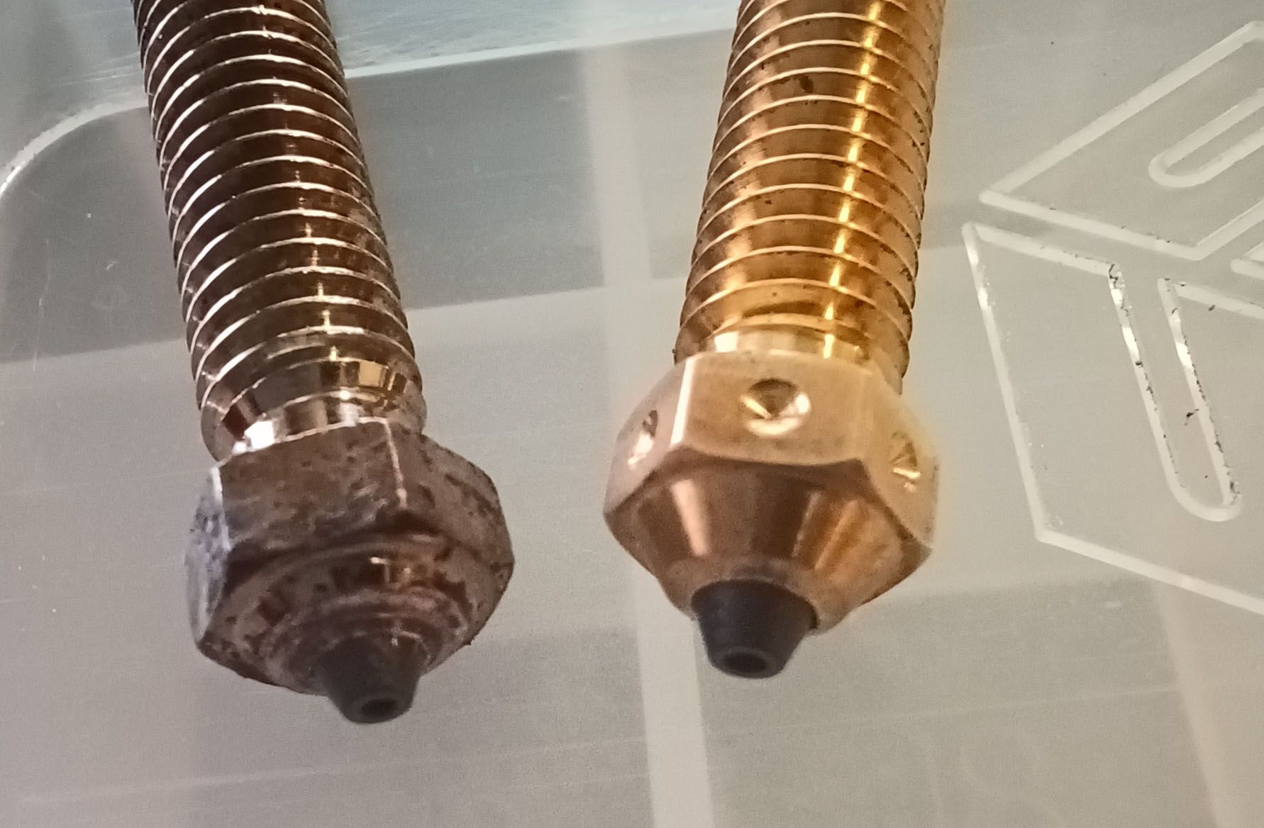
The brass nozzle on the right was used to verify the modifications before doing it to the more expensive copper nozzle on the left.
I tested at 240C printhead temp, which is my current ABS print temp. I lowered the bed to the bottom of travel and just ran the extruder using a G1 E200 FXXXX command.
Using the existing E3D copper/nickel plate supervolcano 0.8mm nozzle I normally run prints with a max extruder speed of 1200mm/min (150mm/sec print speed) which gives very consistent results with no filament dust on the hobbed drive wheel after 12hr prints. At 1500mm/min I start to get sporadic filament slippage but it still extrudes successfully. At 1800mm/min it will not start to extrude and just slips at the hobbed drive wheel.
With the Diamondback 0.8mm tip inserted in a copper nozzle I was able to get consistent extrusion with no filament grinding up to 1800mm/min. At 2000mm/min it would not start to extrude at all and sometimes got stepper stuttering, but at that speed it may also be bumping up against the stepper’s speed limits.
So the quick takeaway is that there is definitely a significant reduction in the force needed to extrude. Combined with essentially no wear, I think it is a no-brainer upgrade. I have no financial interest in this product.
I’ll keep the nozzle in there for the next series of prints and see if I can bump the print speed from 150mm/sec to 180-200mm/sec. Possibly faster for the support printing, as a little loss in quality there is a non-issue. Even a 10% or so speed increase would be great, and considering that the printer is essentially a 6000W heater, the PCD nozzle is also an energy/cost saver.
3dsolex sells a very similar nozzle - a diamond nozzle tip like this. But with the "race" technology (multiple passages for the filament to flow) which speeds up printing a lot.
On 7/10/2022 at 3:48 PM, gr5 said:3dsolex sells a very similar nozzle - a diamond nozzle tip like this. But with the "race" technology (multiple passages for the filament to flow) which speeds up printing a lot.
I saw those, but to me a first step in better heat transfer to the filament is to switch from brass to copper. Branching the main filament passage to several smaller passages seems like adding a bunch of flow restriction. Maybe it is good for a 2.75mm filament, but one reason to stick with 1.75mm is it easier for heat to get to the center of the filament and melt it as plastic is a relatively poor heat conductor.
The Diamondback nozzle tip is a big chunk of PCD that contains the entire transition from the 1.8mm or so filament passage to the 0.8mm nozzle hole. The copper part ends up being a 1.8mm thru hole, so easy to make with a really good surface finish. The PCD tip is a short and stubby part so easier to create smooth transitions for low friction flow than it is to machine smooth transitions at the bottom of a 50mm long, 1.8mm dia hole.
You need to watch this video which proves that the multiple channels is MUCH faster and lower resistance than one big channel even for 1.75mm filament. Bontech worked closely with 3dsolex when developing the CHT. Faster even than the volcano nozzle. I have it queued up at one of the comparison graphs.
Thanks @gr5. That was interesting. I'm not ready to go out and pay $20/nozzle, but for long nozzles with large bores and printing at high speeds (ahem! @coseng), this appears to be a valid approach. At the cool end of the nozzle that triangular land between the three bores would transfer heat to the centerline area of the nozzle. The smaller mass of material within each bore would heat more efficiently.
I generally print with a 0.4 nozzle and my extruder/hot end combination runs out of steam at about14mm³/sec. That is nowhere near the midpoint of the charts in the video. Everything affects everything.
Of course it could just be an advertisement for Bondtech as well. You can never be sure.
No - I totally trust CNC Kitchen. He has fantastic videos and seems extremely honest. You might want to subscribe and watch one of his videos every day. They are just - really informative.
A testing site like CNC Kitchen - if they lied/compromised and got caught - it would ruin their channel forever. They have too much to lose.
Although I'm pretty sure that the effect on a 0.4mm nozzle would be smaller than on the 0.6 nozzle that was tested in CNC Kitchen. And if you go to a 0.8mm nozzle it's so obvious that the multi channels help that even *I* noticed it.
I am a fan of KISS and any attempt to increase heat transfer should start with using a material that has much higher thermal conductivity (4x), like copper. I'd be interested to see if the 3 path brass nozzle is better than a normal bore copper one. But the 3 path one does look cool and has lots of marketing potential. Just to point out, that video is not really a comparison of only heat chamber geometry. The nickel coating of the CHT nozzle provides lower friction than a plain brass nozzle which will on its own increase the flow rate. From this testing it is impossible to attribute the increased flow rate to better heat transfer or less friction. A plain CHT or nickel plated brass nozzle would have been a better comparison.
Copper seems to have a very positive effect, even when it is inserted as a pretty major obstruction in the flow path! Though I am not sure why he didn't just test an all-copper nozzle.
I was already on my second nickel plated copper nozzle, having switched after about 15kg of ABS and 1 of PC. The bore itself was not wearing a lot (yet) but the exit chamfer was getting egged out and the nickel plating on the tip was about 50% worn off. So if the PCD tip prints well its wear resistance will be a cost saver in the long run, not even counting the reduced electricity for a shorter run time. The nickel plated copper nozzle was printing at 60mm3/sec with great results, and the PCD tip may let me increase that to 80 or so, at which point the stepper motor power is not up to the task of higher flow rates. At those rates I get absolutely no filament dust at the pinch drive mechanism after 12hr prints and the extrusion tests are very consistent and drop straight down.
 1
1

ArunC posted a topic in UltiMaker Cura,
.thumb.jpeg.0b7a05eafc09add17b8338efde5852e9.jpeg)
Dustin posted a topic in Firmware,

Recommended Posts
Top Posters In This Topic
43
21
4
Popular Days
Jun 9
8
Jun 2
8
Jun 3
5
Jun 10
5
Top Posters In This Topic
coseng 43 posts
GregValiant 21 posts
gr5 4 posts
Popular Days
Jun 9 2022
8 posts
Jun 2 2022
8 posts
Jun 3 2022
5 posts
Jun 10 2022
5 posts
Popular Posts
GregValiant
How are you powering the bed and hot end? Are they separate from the mainboard (other than control wiring)? Going back through all your photos, I think I'm seeing a persistent problem with extru
coseng
I'm reluctant to start trimming prints since then the tests are not really representative of the thermal operating conditions. I'm in this project about $6k so far and have wasted more filament with
coseng
I love the embedded nut idea! The multiple pauses is dedication! Great idea and flag choices, 😉 I'm going to test the parts on track as-is. There is a lot to be tested for rider ergono
Posted Images
GregValiant 1,251
"No nicked fingers, either!" Now that is a beautiful thing!
I'm a little disappointed though. You seem to be going for this...
While I was hoping for this...
To each their own I suppose.
Link to post
Share on other sites