

What is the direct cause of the under extrusion? Does the filament grind or the stepper skip?
It skips, not grinds.

What is the direct cause of the under extrusion? Does the filament grind or the stepper skip?
It skips, not grinds.
Hey abstract,
I think Illuminarti is right. The teflon piece inside the head seems to be the culprit (and a partially blocked nozzle). If you ask for one, I am sure you'll get one for free. But you can't replace the entire head right now (and you don't want to because taking the rods apart from the sliding blocks isn't that much fun).
The head is not very hard to dismantle. If you decide to do it, you could also take the nozzle apart and put in into a little acetone bath for a few hours. This will flush out any ABS that might got stuck in there.
Here is a little disassembly guide:
And here is the official(?) assembly guide for the UM2:
OK, so here are the results so far:
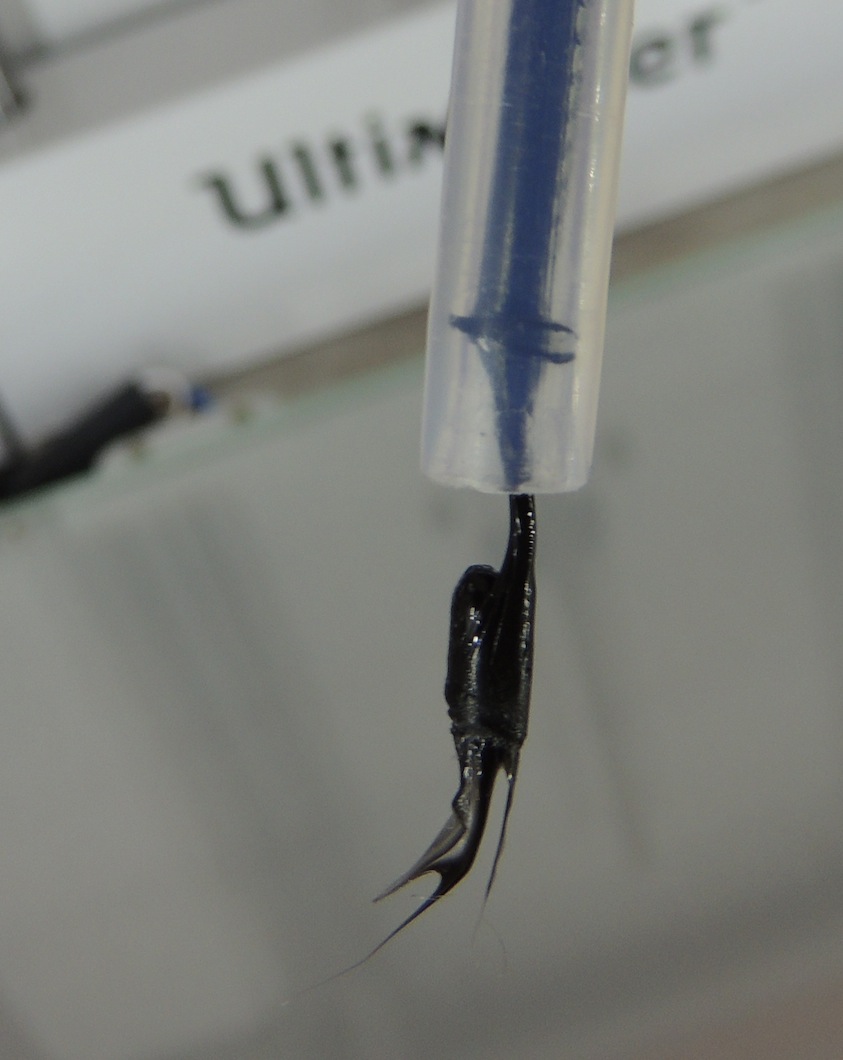
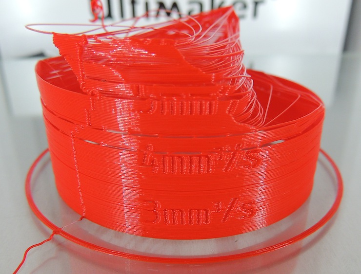
1) Tried the Hot Push - Cold Pull method: Removed bowden tube from head, heated up to 180 degrees, pushed in filament manually until it extrudes, set temp to 90 degress, wait.... at 90 Degrees, sharp pull filament out of head. Repeat until happy.
Below you will see the various pulls, in order

You can see the first one was really nasty, and it got much better with the other pulls.
Doing this test you really start to realise the implication of the curve on the filament - in order to get it into the head from the top you *really* have to straighten it, or it wont go in - so I can start to appreciate the work the bowden tube is doing to resist the curve on the filament.
So, having done that I am feeling really confident, so I go for another print.
However on first attempt to load the filament, it doesn't come out of the head. Looks like its jammed. So, I retract the filament, make a new clean break, really straighten the first few inches, and load it up again.
The resulting print is below..
Hmm... even worse than before....
So, next, I tried a 260 degree flush - again, removed bowden tube, heated to 260 degrees and pushed through as hard as I could.
Now, I reload the filament. Again, it doesn't load properly. Worse this time - I can't retract - its stuck in the tube.
So, I take the bowden tube out again, and here is what I see:
This is not the first time I have seen this in the last 6 months, so this problem seems to recur
Anyway - managed to tidy that up, and I am starting to get a bad feeling about this filament. It is the last 20% of a reel of Ultimaker Black PLA, and it has been on the back of the UM2 in my garage for the last month or so. When I try to snap it, its alot softer than some other PLA (like the stuff inside the house) - so maybe its damp ?
Anyway, I am giving up on this reel of filament, in case that is the cause. I have a short length of Faberdashery RED PLA which has never been tightly wound on a reel, and it has been nice and dry inside....
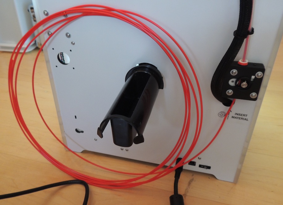
Fingers crossed - I load it up and go for another print:
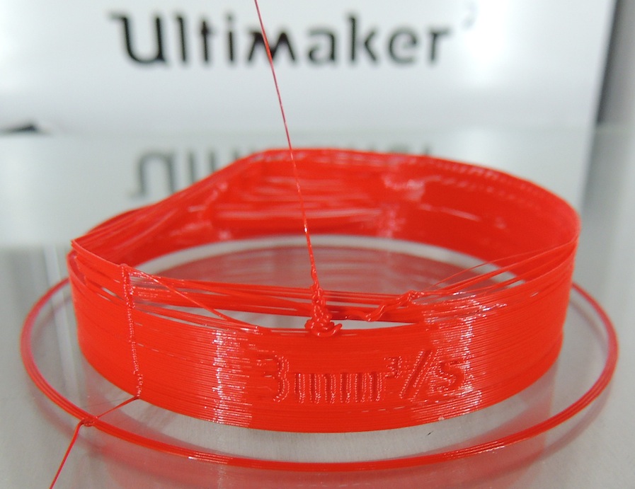
No better. It felt like the flow was improved when it was good - but the extruder still skipped, even part way through the 3mm section.
If I pushed the material REALLY hard through the extruder motor, it DID work better, and didn't skip so much, but it was very tough.
So, I am no further on with results, but I feel like I am getting closer to the problem. It seems that the fundamental problem is that I can't get enough material off the reel and out of the head. There would seem to be 3 possibilities:
1) The Head is still blocked in some way.
2) The Bowden tube system is constricting the movement of the filament
3) The feeder motor cant push hard enough to overcome the resistance to the head.
When I have had the bowden tube off the head, I have used 'move material' and it doesn't seem to have much trouble pushing the filament as far as the end of the bowden tube - so I would like to think I can exclude the actual tube itself.
So, I think we have constriction at the head, causing a bottleneck and the feed motor which is moving at the requested rate has to skip. The constriction seems to 'build up' after the print starts - the first 30 seconds seems OK.
OK, there are my observations. Hopefully the good folks here can apply some analysis and come up with a hypothesis and we can try something else.
Thanks for your input.
Mark.
I still think it is the teflon piece. If this thing is deformed, then the blockage occurs inside the head when the filament softens due to the heat that creeps upward.
And by the way, does the 3rd. fan work?
I still think it is the teflon piece. If this thing is deformed, then the blockage occurs inside the head when the filament softens due to the heat that creeps upward.
And by the way, does the 3rd. fan work?
Yes, all 3 fans work as expected.
here is a photo of the head so you can see the general condition.
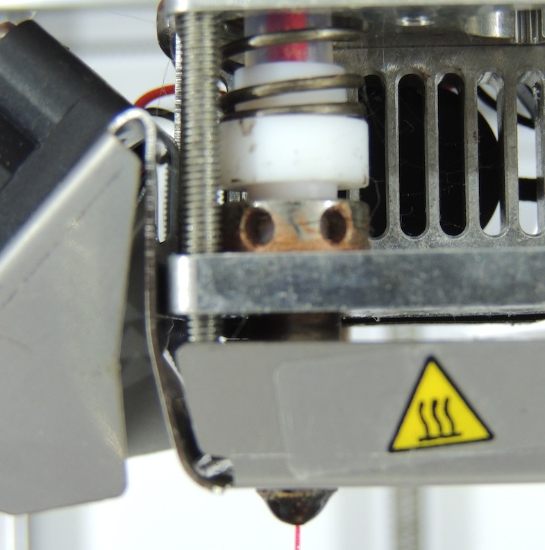
Please could someone describe in detail how I should investigate the state of the teflon piece ?
Thanks
Mark
It's time to take the head apart. It's not hard. The first time will take you 30 minutes. The second time 10 minutes.
Follow Nico's instructions above.
To test the white teflon piece try putting the worst curved black PLA filament through it. The feeder should be able to push about 5kg (around 10 pounds) force so that is your budget. Some of that budget is used to pull in the feeder. Some budget is wasted in the bowden friction. Some in the white teflon part. Most is used up in the nozzle.
1kg force in the teflon part is - somewhat acceptable but not great.
Keep going and take the thin screw with the tiny hex head out which holds in the temp probe and heater. Slide those out and completely take the nozzle off. Burn that sucker to ash (but don't melt it!). I like to put mine in a gas flame for 10 seconds and then remove for 10 seconds and repeat until nothing but ash left. Then holding it with pliers to the 180C to 90C push pull testing and make sure you don't have to push with more than 1kg force to get PLA through. Then clean one more time and soak in acetone to remove any ABS.
Alternatively test your feeder but I don't think it's the problem. Here is a nice feeder test:
http://umforum.ultimaker.com/index.php?/topic/4222-pulling-force-of-um-extruder/?p=34887
Oh and if the white teflon part seems deformed and causing excess friction (it should be zero friction with straight PLA maybe 1/3 kg with curved-last-20%-of-roll filament) then consider drilling it out with a 3mm drill bit.
Also requesting a new teflon part and a new nozzle from Ultimaker will cost you... nothing. I believe they don't have the software to bill you so they just give it away.
I'm starting to think that the best fit for the problem machines would be a smaller than expected nozzle, it seems to be the one component that no-one has changed. By my reasoning if the slicer thinks the nozzle is 0.4mm but it's smaller, it will be trying to feed too much through it, building up pressure and something has to give, which turns out to be the stepper skipping (probably the best outcome in this situation). Over time the continuous over-pressure stresses the other components leading to deformation of the teflon coupler and the performance degradation over time that people see.
Another thing that hints in that direction is posts I've read where people have dropped flow rate which seemed to help, sometimes as far as 80%. If I drop it even to 98% I get immediate and very visible under extrusion.
Would it be possible to test this by gradually and slightly reducing the configured nozzle size to see what effect that has? Would that do what I think it will and cause the slicer to request a lower feed rate (perhaps together with keeping the wall thickness an integer multiple of the configured nozzle size)? Of course if there is a way to accurately measure the actual nozzle size that would be better.
In my uneducated expectation (software guy), ignoring viscosity related scaling issues the pressure would be related to the area of the nozzle opening, so a nozzle opening 0.358mm in diameter would mean that a flow rate of 80% would be correct, not that big of a difference.
Edit: grammar
It's time to take the head apart.
OK,
Tomorrow the head is coming apart.
The more I think about it, the more I buy the 'nozzle opening' theory. This is (by its very nature) the 'bottleneck' of the entire system, and if its smaller than 0.4mm, presumably the filament *has* to back-up if the flow rate is based on a 0.4mm hole.
I have heard people talking about needles of the appropriate diameter to clear the nozzle. Otherwise I guess the 'burn-it-out' method sounds plausible.
I guess I would quite like to get a 0.4mm needle through the hole just to be sure.
Will let you know how it goes tomorrow. I have requested new teflon and nozzle from UM.
Thanks for all the encouragement.
Cheers
Mark
So, on the theory of the nozzle size.
I measured the little tips hanging out the top of these:
They all come up as 0.37mm and 0.38mm diameter.
These are now cooled and they came back up through the nozzle when I pulled, so I am not sure whether we expect them to be 0.4mm in this state.
Any comments ? Anyone else tried this test and measured them ?
Thanks
Mark
I measured mine - it is exactly 0.4mm. If I squeeze the digital caliper a bit I get 0.39.
Nico and I did several sewing-needle-in-nozzle hole tests. But keep in mind that many of these printers that are having trouble were working fine for the first week or month.
Here is an interesting way to measure the hole - post #443 is nico result:
Post #490 was my result:
Much more likely it is the white teflon isolator which deforms slowly over weeks under high heat or just general gunk in the nozzle. I print mainly only up to 230C (although occasionally 240C) so maybe that is why mine lasted longer?
I mean think about it - probably all these nozzle were drilled with the same drill bit in some factory somewhere. You can't drill a hole smaller than the drill bit.
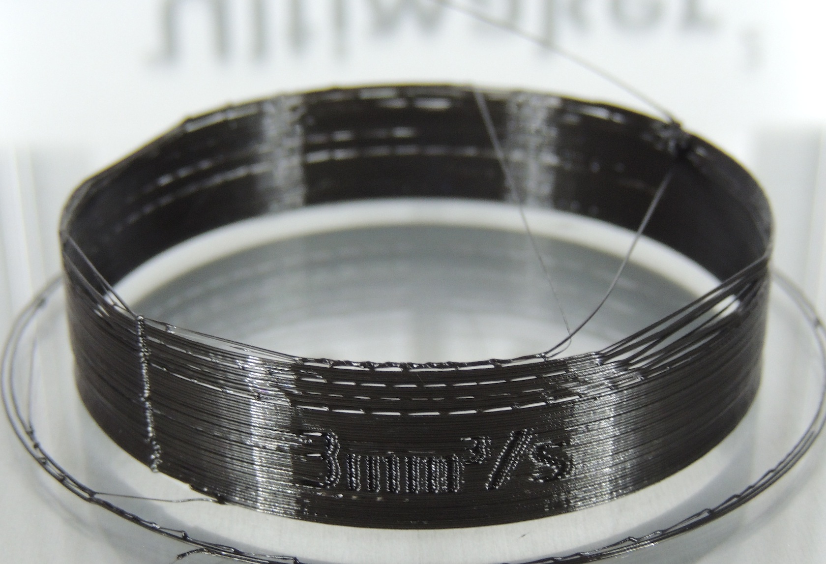
OK, so today I started testing based on the theory that the 'clear' nozzle size is less than 0.4mm. I also wanted to see what temperature does.
So, instead of the default setting (210 ? at 100% flow), I tried the following:
230 degrees, with 90-95% flow (manually fiddling)
240 degrees with 95% flow
interestingly it ejected that little thread of black (from 3 prints ago) halfway through the print. although it might have come from the *outside*of the nozzle (which still has lots of black on it).
Given that I measured the threads at 0.38mm and also this filament is about 2.9mm, one might expect the flow rate to be required as (0.38/0.4) * (2.85/2.9) * 100 which would be about 93.5%.
Clearly either the rate or the temperature has improved the printing (marginally...), but I feel like we are getting a bit more scientific with matching the available flow rate with the supply rate.
Also, I have noticed that we get some minor under-extrusion (*without* a motor kick) as the print rate changes in this model - looks like the speed of movement increases before the flow rate has increased - this leads to one 'thin' section of one of the early layers in each section. I think we can ignore that for the purposes of testing.
Gonna take a closer look inside the head next.
Mark
I mean think about it - probably all these nozzle were drilled with the same drill bit in some factory somewhere. You can't drill a hole smaller than the drill bit.
But somehow people are measuring variances, so however it is happening, it is
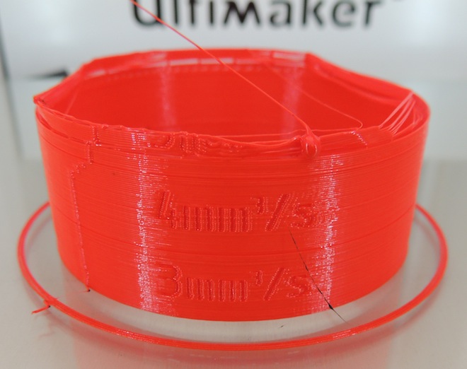
abstract: would be interesting to see a print just changing the flow to 96% with the temp at 210C to better compare the result to your earlier test with the red filament.
What does your filament look like from the section that the feeder was driving at 4 and 5 mm3/s? Are the tooth marks clean and spaced the same as the section fed at lower rates?
OK.
more info,
1) After the last test where the feeder had skipped at 4-5mm, I noticed nicks in the filament, inside the bowden tube. Its possible that these get more blocked when they hit irregularities inside the teflon tube (see below). So the Feeder *is* chewing up the filament a bit as it skips, and this might exacerbate the problem by creating more resistance when those nicks hit the teflon.


Next - Hot End !!
I dismantled the head, to take a closer look at the teflon.
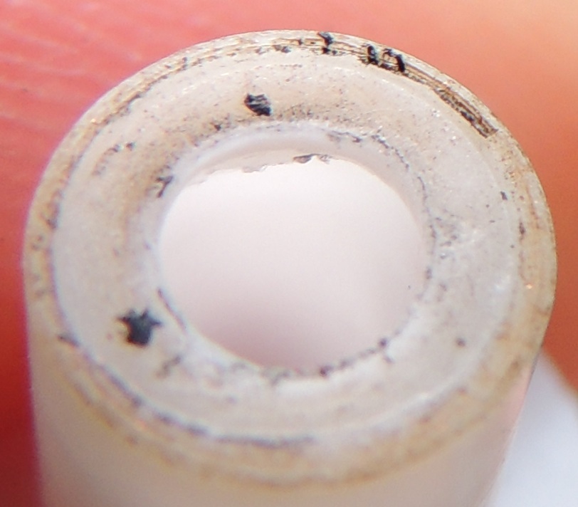
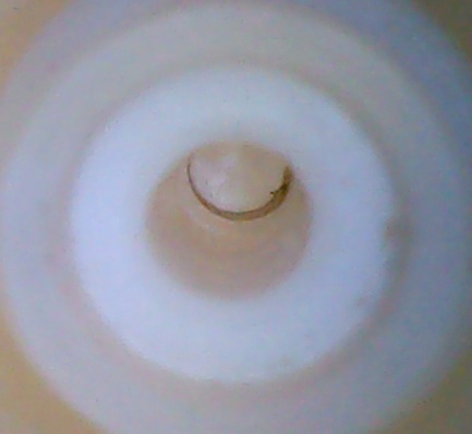
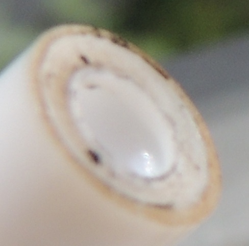
As suggested previously, it does appear that my teflon is compromised. You can see that there has been melt-compression around the hot end, and the teflon has deformed, creating a circular rut (ring) just inside the hot end before it hits the metal section. This has the effect of 'catching' any irregularities in the filament, for example when loading, the flat sharp end of the filament can get stuck in the rut and this prevents it advancing. I would also expect that the filament nicks made when the feeder skips would ALSO catch in this rut, creating a knock-on jam which makes more nicks etc etc. Catch 22.
Going to think what to do next. Suggestions welcome.
Mark

Wow that filament is grinded a lot. Maybe it's the picture but mine doesn't seem to be that marked.
I think that all of this is caused by the teflon. You can probably ask Ultimaker support to have one replacement part
That filament looks pretty mangled, and looks like it's been fed through twice, the first time seemed ok, the second not so much. Retracting does this I guess so it's probably ok, but in this case the teeth marks aren't aligned with the previous ones so maybe that compromises the traction?
OK, so I am trying visualise the path of the filament through the hot end, to see where it might get snagged, apart from simply being constrained by the nozzle : I can see 2 places.
First here is a breakdown of the parts:
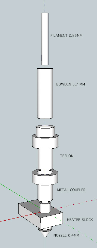
and here they are assembled:

Some parts are HOT and some COLD and *maybe* some are 'WARM' ??
The heater block and nozzle are definitely HOT, and any material inside these bits will be molten, and presumably wont 'snag'
I am not sure what the temperature state of the 'metal coupler' is. Since its screwed into the heater block I would guess its pretty hot - and the 3rd fan is doing its best to cool this. Judging by the heat damage to my teflon piece, I guess its not doing a perfect job and the teflon is also getting pretty hot.
Now... how hot ? Hot enough to melt the filament ???? or just make it pliable ? Presumably if its pliable, it may also be losing its stiffness in the teflon / coupler stage, and this may mean that the mechanical movement of the filament behind it may NOT be full transferred into moving the filament in the Teflon / coupler stages. So, we are probably getting deformation of the filament here, and it might even be squeezing back from the nozzle up to fill any void in this area. Teflow is non stick and presumably this stops filament sticking and drying on the teflon.
So, it would be nice to know the state of the filament as it passes through this sequence of pieces.
I made a movie of the path through the hot end, and there are 2 places where we have potential 'voids' - they are the white rings in the movie below:
The first white ring is where the Bowden tube sits inside the teflon piece. I presume this should be pushed as hard as possible to make this ring zero. I think the temperature here is cool, so no chance of melting and filling this void - BUT this is a 'catch' point for any dings in the filament - such as those in my red filament photo in an earlier post. So we could get some resistance here.
However, lets think about the second white ring, which is the junction of the teflon and the heater block *inside* the metal coupler. This gap is HOT - presumably very hot. The teflon appears to be pushed in using the spring, I suppose to close up this gap - but I can't tell if it makes a flush fit (anyone know ??) - however, whenever we pull out filament from the hot-in cold-out cleaning method, I see a plastic ridge from about this point, which suggests there is a gap here. However, these ridges may also be from the rut just inside the bottom of my teflon piece.
I would like to think that this gap between the pieces is hot enough that its NOT going to catch any filament dings. However the rut in the teflon probably is not so hot
Here is a good example of the effect on the filament:
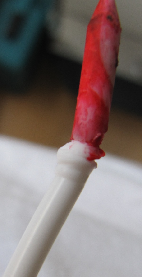
So, anyway - there are my observations on the hot end.
Analyse away - and let me know what you think I should do next to get myself printing more than 3 cubic mm/sec
Mark
Normally about 10 degrees (outside) but for the last 3 tests and hot end investigation I have brought UM2 indoors where its 20 degrees
Doesn't seem to have helped.
Thanks
Mark

ArunC posted a topic in UltiMaker Cura,

.thumb.jpeg.0b7a05eafc09add17b8338efde5852e9.jpeg)
Dustin posted a topic in Firmware,


Recommended Posts
Top Posters In This Topic
52
47
38
37
Popular Days
Feb 27
30
May 6
28
Mar 6
24
Mar 3
24
Top Posters In This Topic
illuminarti 52 posts
gr5 47 posts
schafe 38 posts
Nicolinux 37 posts
Popular Days
Feb 27 2014
30 posts
May 6 2014
28 posts
Mar 6 2014
24 posts
Mar 3 2014
24 posts
Posted Images
abstract 3
I am in London, England.
I am going to try the hot push cold pull thing, and also the 260 degree flush thing you mentioned.
I am partly tempted to dismantle the hot end, but since its not 'broken' at present I am a little reluctant.
Maybe I can buy a replacement teflon and print head ? if I am going to dismantle I might as well replace.
The manual feeding of filament and pushing hard certainly helps, but not beyond 4mm - so I can see that tidying up the filament feeding will be a longer term project.
For now I really think I must have an obstruction preventing me going past 3-4mm - so I will focus on clearing the head first.
Will let you know how this first step works out (hot in cold out, and flushing at 260). I will also put on a new spool with full radius.
I really think this 10mm test thread has done a long way to rationalising and understanding under-extrusion. Often if you can measure something like this up to a guaranteed point of failure, its much more helpful than trying to diagnose random failures from time to time.
Thanks.
Mark
Link to post
Share on other sites