Jump to content

Top Layers not touching - UM2


Nicolinux

Recommended Posts

Posted (edited) · Top Layers not touching - UM2

@esteban-pacheco: I owe you a test print like a said a while ago. Since you did not provide all print settings I printed a 25mm X 25mm x 5mm square with the following additional settings:


  • layer height - 0.2

  • speed - 40


It looks like this:

square.thumb.jpg.8f0c14f9036d70362c8c0250a55619e9.jpg

Perfect surface - WTH!?!??


Well well, i told you those settings are working, but is wise to raise the material flow and the temperature to those levels?

Edited by Guest
  • Link to post
    Share on other sites

    • Replies 526
    • Created
    • Last Reply

    Top Posters In This Topic

    Top Posters In This Topic

    Posted Images

    Posted · Top Layers not touching - UM2

    Alright I got an humidity scale (or whatever it is called). When I put it right in front of the UM2 it measures 68%. On top of the UM2 it is even more - 71%. I guess that's quite a lot.

    @DoctorH: What did you measure? It seems my entire appartment is pretty "wet". There is no spot that's under 60%...

  • Link to post
    Share on other sites

    Posted · Top Layers not touching - UM2

    Oh and there is something else too - forgot to mention it. As of the last two PTFE coupler changes, I noticed that when the filament passes the spot where the coupler, the metal collet and the Olsson Block meets, it snags onto something and has a very hard time to pass. Then when the pressure builds up, it snaps and passes with great speed. This can't be good under-extrusion wise. I wonder what it could be. I have checked both the coupler and the collet and also the Olsson Block. The connection should be smooth. I can't really test for gaps because there is no way to look "inside" where the filament passes while it is assembled.

    I have searched for an endoscope camera but there is nothing consumer grade to be found that's thin enough.

    I should have counted how many times I have disassembled the head until now. I think I am close to the three digits :)

  • Link to post
    Share on other sites

    Posted · Top Layers not touching - UM2

    I should have counted how many times I have disassembled the head until now. I think I am close to the three digits :)


    There should be a badge for that too :p

    This took an interesting angle.

    I'll see if we have a way to measure humidity in the office.

    • Like 1
    Link to post
    Share on other sites

    Posted · Top Layers not touching - UM2

    Hi.. umm

    Long history short: Try to remove the feeder cable from the 'haul' of cables to isolate it.

    Long history:

    Long history long:

    I have an umo+ (same board as um2). My main head (dual heads magnetic changer) had been doing the top layers wrong. This week I was setting the first batch of final production products (unrelated) so I started to print with the good Faberdashery and all the top layers, for gcode I did set a month ago, where showing under-extrusion on the top layers, not the perimeters, just the top layers.

    I was also testing some beta stuff, and I though that as the problem but no. I did also took out the feeder motor to rearrange some unfinished cables. And when I did that the print quality on the top layers went back to normal. So...

    Ok the history even longer:

    (to explain some background about why I have touch the cables.

    Two/Three weeks ago I had the transistor of my board (um2.1.1) and after soldering the new transistor. Just because I wanted to 'clean' a bit the bottom of my printer I rearranged all the cables (so they are more close to each other and they are properly gripped by the velcro on the umo+ bottom). After I fixed that I have been printing in white, transparent and crappy filaments. I have 'now' check all that printed stuff and the top layer do show less material, but I didn't notice just because I was just printing stuff to make a wiper for my dual magnetic bla bla bla..

    Ok so, after 3 days wasted testing stuff, changed bowden, ptfe coupler, cleaned and even boiled the hotend isolator barrel to clean even more. Nothing did help. So I took apart the feeder (I use um2 feeder model bough to ultimaker on a umo+ with the @ataraxis adapter). So stuff I have in common with a um2:

    - Same board um2.1.1

    - Same feeder motor with IRobertI, except I use mk7, that I have calibrated and recalibrated just to be sure.

    - Same gt2 belts (not the same size, but same steps)

    - A lot more of cables going down the first head

    List of cables that go 'together' on my setup:

    - x2 fans 24v to the fan pwm

    - x2 fans to the 19-24v output connected to a pwm manual controller (always off unless I use dual, and that isn't the case)

    - x2 fans 5v to the 5v fan output, like um2, but in my case they point to the peek upper area.

    - Heater, pt100, X motor, First extruder motor.

    So I have photos to show the 'before' and 'after' of separating the feeder cable from the stream of cables, but I can't show them public because it's a product I'm going to sell in the following weeks. So if anyone wan't the photos just pm.

    I'm thinking to get some Ferrite block to place it on the feeder cables to test further insulating the cables. For my it works, I hope for someone else too.

    Theory short:

    Because there's a lot of cables together, the noise it's transmitted to some of them causing electrical noise. I won't be able to get my friend that has an Oscilloscope to check this any time soon, but I bet some other user with the problem might have one to check the electrical noise on the feeder when fans, heat, etc it's on.

    Cheers!

  • Link to post
    Share on other sites

    Posted (edited) · Top Layers not touching - UM2

    Hm, I don't know... I hoped this is the solution, but for me - it is not.

    Here is what I did:


    1. Updated the firmware to the latest stable version (15.04.x).
    2. Disassembled the head and replaced the PTFE coupler.


    Then I printed a square with the following settings (I did abort the print right after the bottom was finished):


    • layer height - 0.2
    • infill - 0
    • speed - 50
    • temperature - 215


    It looks like this... There is even under extrusion on the outer walls :(

    first_1.thumb.jpg.edc39113cb55b34d612830f1f7c1585a.jpg

    first_2.thumb.jpg.9e4328ff916444f62203dca8c0a3394b.jpg

    Then I removed the board cover at the bottom and re-routed the feeder cable. It looks like this:

    um2_back.thumb.jpg.2c0194ed9f4ddd6932511c86425da51e.jpg

    Then printed the same .gcode file again. No under extrusion on the outer walls, but still sucky surface.

    second_1.thumb.jpg.08114dbb505c36eaf9846a02ab0ce798.jpg

    second_2.thumb.jpg.4e79caa64065bc1d2eeab3b1fc3d0372.jpg

    I hate this issue.

    first_1.thumb.jpg.edc39113cb55b34d612830f1f7c1585a.jpg

    first_2.thumb.jpg.9e4328ff916444f62203dca8c0a3394b.jpg

    um2_back.thumb.jpg.2c0194ed9f4ddd6932511c86425da51e.jpg

    second_1.thumb.jpg.08114dbb505c36eaf9846a02ab0ce798.jpg

    second_2.thumb.jpg.4e79caa64065bc1d2eeab3b1fc3d0372.jpg

    Edited by Guest
  • Link to post
    Share on other sites

    Posted · Top Layers not touching - UM2

    Oh men sorry :S

  • Link to post
    Share on other sites

    Posted · Top Layers not touching - UM2

    um2_back.thumb.jpg.2c0194ed9f4ddd6932511c86425da51e.jpg


    Hey Nicolinux

    THIS can help keep those cables tidy around your feeder :p

    I feel your pain, just when you think you have a really good print going you see lines not touching. I tried everything I could think of on mine and just couldn't get it to print right. But there has to be a cause. My replacement printer doesn't have any issue at all and i have really pushed it so it shouldn't be environment or material.

  • Link to post
    Share on other sites

    Posted · Top Layers not touching - UM2

    Hey guys,

    So last week i went to a training @ Ultimaker (and had a great time). So back home i decided to give my old UM2 a good maintenance.

    So i changed the Teflon and the steel coupler that i destroyed.

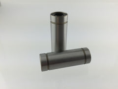
    Re-positionned the linear bearing in the head: This is one thing i learned during the training.

    When you watch the bearing you can see the balls inside. There are four lines of balls. To reduce wear on these bearings you have to place them in the head with the line of balls that form an X and not a +.

    Doing this i noticed that one of my bearing was pretty rough.

    Lubed the rods with some sewing machine oil.

    Clean and greased the Z screw.

    Put everything back in place, so let's go for a test print. I had a calibration cube that i used previously in this thread, so i tried it. It shows clearly the top layers not touching.

    So i tried various things, and the one for the moment that gave the best results was tightening the short belts.

    It's not perfect but now the not closed lines appear mostly in the center of the test cube (i can show pics if needed).

    I suspect that the linear bearing that is a bit weared out could be the cause. I feel more "friction" on that one than on the other one, i think i'll probably try to replace the linear bearings to see if it has any effect.

    But most important thing: Short belts tightened as much as possible!

    • Like 2
    Link to post
    Share on other sites

    Posted · Top Layers not touching - UM2

    @DidierKlein - Your review is very interesting and practical. However, one pic worth 1K words.

    Can you perhaps make some illustrations to highlight the explanations?

  • Link to post
    Share on other sites

    Posted · Top Layers not touching - UM2

    Thanks for the x+ bearing tip. Never thought of that...

  • Link to post
    Share on other sites

    Posted · Top Layers not touching - UM2

    @DidierKlein - Your review is very interesting and practical. However, one pic worth 1K words.

    Can you perhaps make some illustrations to highlight the explanations?


    I'm planning to do a tutorial on my website soon but i'll have to take one printer apart for that :) or do you mean the test prints? I'll take pics of that tonight


    Thanks for the x+ bearing tip. Never thought of that...


    Me neither, it's a tip that Denis from Ultimaker gave us, it's almost sure that anybody that takes the four lead screws off will put the bearing back the "wrong" way.

  • Link to post
    Share on other sites

    Posted · Top Layers not touching - UM2

    Didier, which bearing do you mean? I don't get it. The linear bearing on top of the head? You have to pop out the thin rods in order to take it off right? I always wanted to avoid that.

  • Link to post
    Share on other sites

    Posted · Top Layers not touching - UM2

    I think Didier meant the 2 bearings inside the printhead.

  • Link to post
    Share on other sites

    Posted · Top Layers not touching - UM2

    Ok, so the linear bearings right?

  • Link to post
    Share on other sites

    Posted · Top Layers not touching - UM2

    Didier, which bearing do you mean? I don't get it. The linear bearing on top of the head? You have to pop out the thin rods in order to take it off right? I always wanted to avoid that.


    As Sander says i mean the linear bearings inside the head:

    1602b56bc6021a3e34b9190dd1e8b548_medium.jpeg

    And yes indeed you have to remove the rods to take them out of the head. On my UM2 i never removed the rods but they where not in the "correct" position. I dismantled the head quite a few times and they can move freely when the lead screws are not screwed.

    Taking the rods out is quite easy and putting them back also.

    To take out: push for the long one and pull for the short one.

    The bigger one goes from left to right (as a reminder the longer one goes like the longest part of the head (the side fans) and the shorter one from front to back.

    To put back the long one it must be just on nail far from the left panel (when facing front).

    The short one must be just showing out of the front sliding block (or it will hit the Z rods).

  • Link to post
    Share on other sites

    Posted · Top Layers not touching - UM2

    Hey Didier, sorry to be so thick headed, but I don't understand what you mean with the alignment of the four lines of the bearing balls. To me these lines look a bit curved at their ends. But everything is static and symetrical. Or can one relocate/move the inside of the ball bearing? Here is a picture:

    lb1.thumb.jpg.d68e782bfde76a96dffe60eee7e0ccfd.jpg

    As for the short belts, I do remember that tightening these did have some impact on the surface quality, but more on the fact that the walls/shells didn't touch each other. Looking at my last two squares, that's definitely the case too. However, last time I tried to tighten the belts, I had a very hard time to get one of the belts really tight. It seemed that no matter what I tried, it wouldn't keep the tension. I think I need to file down the stepper motor holes a bit so I can push the stepper down and tighten the short belt(s) more.

    lb1.thumb.jpg.d68e782bfde76a96dffe60eee7e0ccfd.jpg

  • Link to post
    Share on other sites

    Posted (edited) · Top Layers not touching - UM2

    Hey Nicolinux

    THIS can help keep those cables tidy around your feeder :p

    I feel your pain, just when you think you have a really good print going you see lines not touching. I tried everything I could think of on mine and just couldn't get it to print right. But there has to be a cause. My replacement printer doesn't have any issue at all and i have really pushed it so it shouldn't be environment or material.


    Hey Labern, sorry I missed your reply. I already have it on my radar. Next time I need to print Robert's feeder, I'll take your mod. Thanks!

    Edited by Guest
  • Link to post
    Share on other sites

    Posted · Top Layers not touching - UM2


    @Nicolinux: Do you always print without the filament guide of Robert's feeder?

  • Link to post
    Share on other sites

    Posted · Top Layers not touching - UM2

    Hey Didier, sorry to be so thick headed, but I don't understand what you mean with the alignment of the four lines of the bearing balls. To me these lines look a bit curved at their ends. But everything is static and symetrical. Or can one relocate/move the inside of the ball bearing? Here is a picture:

    lb1.thumb.jpg.d68e782bfde76a96dffe60eee7e0ccfd.jpg

    As for the short belts, I do remember that tightening these did have some impact on the surface quality, but more on the fact that the walls/shells didn't touch each other. Looking at my last two squares, that's definitely the case too. However, last time I tried to tighten the belts, I had a very hard time to get one of the belts really tight. It seemed that no matter what I tried, it wouldn't keep the tension. I think I need to file down the stepper motor holes a bit so I can push the stepper down and tighten the short belt(s) more.


    If you look at the bearing from the front and you see the lines of balls, if you rotate it the 4 lines can form an X or a +

    You cannot move the inside it's just how you put the bearing in the head housing that matters

    What Dennis from Ultimaker told us was the X position weared out the balls less than the + position.

    For the short belts you are right but for me the difference was really big for the top layers so i thought it was worth mentionning

  • Link to post
    Share on other sites

    Posted (edited) · Top Layers not touching - UM2

    Alright, I worked on this issue again. Here is what I did:

    Disassembled the head again, took out the short rods, checked the linear bearings (alligned them X-Men style) and assembled everything again. Tightened the hell out of the short belts (again). Nothing changed :/

    I printed the test square and aborted the print after the bottom was done. Here is the .gcode file. Print temp 215°.

    https://www.dropbox.com/s/8vilrm5zir0neiw/20mm-box.gcode?dl=0

    That's right after I have assembled everything:

    after_maintenance.thumb.jpg.cfb558e1323b3234c1110559a38603ae.jpg

    Printed it again, this time with fans off:

    no_fans.thumb.jpg.61592c23b1c3f5030ac8e464ae9bbdb7.jpg

    Printed again with fans on and flow at 105%:

    flow_105.thumb.jpg.a71ed9fe7f5e3a371a4ea5dbdb41f5a4.jpg

    And one last print with 220° instead of 215°:

    temp_220.thumb.jpg.61f0176d2db1cbbd480a0732da5b748a.jpg

    During the maintenance I noticed something else. When the head is assembled there is one possibility to align the nozzle in the wrong way. This might add resistance to the filament because the PTFE coupler is not perfectly aligned with the metal collet and nozzle.

    tilted_nozzle.thumb.jpg.11c1599e17541263d78fd06659afea5a.jpg

    And there is something else too. The spot where the PTFE coupler meets the nozzle should be tight and leave no gap since filament would expand and get caught up in there. It seems that the metal collet tilts the PTFE coupler slightly which leads to a gap on one side:

    filament_snag.thumb.jpg.b41c52114e8a2d4f692eafbfb2ddddc6.jpg

    On the right side, if you look through the hole, you can see a dark seam. That's where the gap is. On the left image, the seam is barely visible. I tested it with a dentist's tool (no dentist was harmed in this process):

    dentist_tool.thumb.jpg.c7862d1654ebc54b64b70f966b8e75d0.jpg

    filament_snag_test.thumb.jpg.444317531b05d2ac3b742544aa3b9969.jpg

    When I move the pointy end over that seam, on the left side I feel no resistance. But on the right side the tool snags onto that gap. The gap coincides with the rotation of the metal collet. If I turn the collet by 180° the gap would be on the left side while the right side is tight.

    I tried this with two different metal collets and different PTFE couplers. Also tested it with an experimental Olsson Block for 1.75mm filament. There it is the same.

    This might be the reason for the filthy under extrusion, but then I wonder why others don't have any problems with it.

    Btw. one tip about tightening the short belts. If you position the head in the center and tighten the belts, you might not be able to match the tension of the belts on the x and y axis. Try to move the head around and look for a spot where there is the most slack on one belt. Then tighten the hell out of it and repeat for the next belt. That was the only way to get the x axis on my UM2 to match the tension of the y axis.

    after_maintenance.thumb.jpg.cfb558e1323b3234c1110559a38603ae.jpg

    no_fans.thumb.jpg.61592c23b1c3f5030ac8e464ae9bbdb7.jpg

    flow_105.thumb.jpg.a71ed9fe7f5e3a371a4ea5dbdb41f5a4.jpg

    temp_220.thumb.jpg.61f0176d2db1cbbd480a0732da5b748a.jpg

    tilted_nozzle.thumb.jpg.11c1599e17541263d78fd06659afea5a.jpg

    filament_snag.thumb.jpg.b41c52114e8a2d4f692eafbfb2ddddc6.jpg

    dentist_tool.thumb.jpg.c7862d1654ebc54b64b70f966b8e75d0.jpg

    filament_snag_test.thumb.jpg.444317531b05d2ac3b742544aa3b9969.jpg

    Edited by Guest
  • Link to post
    Share on other sites

    Posted · Top Layers not touching - UM2

    I reported the issue with friction caused by the screw that holds the heater & PT100 already 2 times, last time here;

    https://ultimaker.com/en/community/view/17494-dual-olsson-block-for-easy-pla-abs-switching-on-ultimaker2#reply-120281

    Easy to solve by drilling out the hole in the assembled cooling-block a bit.

    • Like 1
    Link to post
    Share on other sites

    Posted (edited) · Top Layers not touching - UM2

    @nicolinux , Although I don't share your passion for top layer analysis :)I couldn't resist giving your gcode a try. Here's the results. In real life it has never bothered me before .....

    First Red Colorfab pla, UM2, olssonblock, 0.4 jet nozzle from 3dsolex, 100% fan

    215 - 50mm/s  

    215c.20151013_220048.thumb.jpg.bec14ee3b0b5f6baf963ae084561728b.jpg

    215 - 30mm/s

    5a331279867db_21530mm-s.thumb.jpg.8a1184c5d7637a211a2ffac1fea9e0dc.jpg

    205 - 50mm/s  

    5a331279d18ab_205celsius50mm-s.thumb.jpg.a8cc3c62bbae3ec8d10281d8eb9646ad.jpg

    and last, and better, Ultimaker white ABS, E3Dv6, 30% fan, 0.4 jet nozzle

    50mm/s 255 (fluctuating 249-259 but thats another problem...)

    5a33127a1f7ac_255umabse3dv6.thumb.jpg.875d70c754777fa02ca5687d098d24c8.jpg

    215c.20151013_220048.thumb.jpg.bec14ee3b0b5f6baf963ae084561728b.jpg

    5a331279867db_21530mm-s.thumb.jpg.8a1184c5d7637a211a2ffac1fea9e0dc.jpg

    5a331279d18ab_205celsius50mm-s.thumb.jpg.a8cc3c62bbae3ec8d10281d8eb9646ad.jpg

    5a33127a1f7ac_255umabse3dv6.thumb.jpg.875d70c754777fa02ca5687d098d24c8.jpg

    Edited by Guest
    • Like 1
    Link to post
    Share on other sites

    Posted · Top Layers not touching - UM2

    Thanks for the infos @ultiarjan. So I take it you are a believer now? :)

    Usually this issue doesn't bother me either when I print "organic" shapes. But for exact geometric forms with large flat surfaces it looks stupid and cheap.

    I'll try your tip about enlarging the hole for the grub screw when I'll disassemble the head again.

  • Link to post
    Share on other sites

    Posted · Top Layers not touching - UM2

    Wait a second... I know this bottom surface from somewhere o_O


    Check out at 0:15 and play it in slowmo.

  • Link to post
    Share on other sites

    Create an account or sign in to comment

    You need to be a member in order to leave a comment

    Create an account

    Sign up for a new account in our community. It's easy!

    Register a new account

    Sign in

    Already have an account? Sign in here.

    Sign In Now

    • Our picks

      • UltiMaker Cura 5.7 stable released
        Cura 5.7 is here and it brings a handy new workflow improvement when using Thingiverse and Cura together, as well as additional capabilities for Method series printers, and a powerful way of sharing print settings using new printer-agnostic project files! Read on to find out about all of these improvements and more. 
         
          • Like
        • 16 replies
      • S-Line Firmware 8.3.0 was released Nov. 20th on the "Latest" firmware branch.
        (Sorry, was out of office when this released)

        This update is for...
        All UltiMaker S series  
        New features
         
        Temperature status. During print preparation, the temperatures of the print cores and build plate will be shown on the display. This gives a better indication of the progress and remaining wait time. Save log files in paused state. It is now possible to save the printer's log files to USB if the currently active print job is paused. Previously, the Dump logs to USB option was only enabled if the printer was in idle state. Confirm print removal via Digital Factory. If the printer is connected to the Digital Factory, it is now possible to confirm the removal of a previous print job via the Digital Factory interface. This is useful in situations where the build plate is clear, but the operator forgot to select Confirm removal on the printer’s display. Visit this page for more information about this feature.
          • Like
        • 0 replies
    ×
    ×
    • Create New...