Jump to content

Exploring Marlin Bed Auto Level


Recommended Posts

Posted · Exploring Marlin Bed Auto Level

He folks!


Since the latest Marlin firmware features the Bed Auto Level function we we’re interested in finding a good hardware solution for our Ultimaker Original.


First we tried the this sensor for auto leveling.


14875553848_307b865ef3_z.jpg


On our second try we decided to give this sensor a go and modelled a mount so we could attach it to the hot-end of the Ultimaker. This mount isn’t great, it’s already bending under the stress and heat, but good enough for an initial quick test.


These are the first results we got from the sensor, doing 6 measurements at 4 points on the build platform.


14875620069_494542f12d_z.jpg


Right now the sensor probably won’t fit the original Ultimaker hot-end. We’re looking for a sensor that will fit the original Ultimaker hotend, features good range and is accurate. We’ll be updating this thread with our results and hope to hear ideas or tips that we can look into.


cheers,

Gijs


  • Like 2
Link to post
Share on other sites

Posted · Exploring Marlin Bed Auto Level

1# update on our progress on the z-probe / auto-level / easy-level project

We made a couple of prints on the ultimaker outfitted with the z-probe. They were going great once the offset from the printer's nozzle was calibrated. Which brings me to an issue that arose; I was able to go into the settings of the ultimaker to correct the z-offset but after shutting down the printer, the value was set to the default firmware value. Does somebody know how I might be able to save this value? I thought the feature of saving for example the PLA preheat temperatures in the eeprom was present in past firmware versions.


If you get a shorter one, couldn't it be made to fit the hole for the 2nd hot end in the head, maybe threaded i the aluminum plate?


@Meduza

The sensor that we have right now is the LJ12A3-4-Z/BY. The diameter of this probe is 12mm, it will not fit in the printhead housing without some serious ultimaker surgery. It has a detecting distance of 4mm.

$T2eC16V,!yUE9s6NEm!rBQF5gfw5RQ~~60_35.JPG

Luckily there is a 8mm sensor out there, which in theory will fit inside the printhead. (for example the LJ8A3-1-Z/BY) Only problem; the detecting distance; it is only 2mm :(

41qNIArjNcL._SY355_.jpg

These type of cylindrical inductive proximity sensors are available in many different configurations, a nice overview can be found here: http://www.ia.omron.com/products/category/sensors/proximity-sensors/index.html

Which brings me to the next sensor which I happen to have ordered ;) It's name: TL-Q5MC1

41qpYoMTwCL._SY300_.jpg

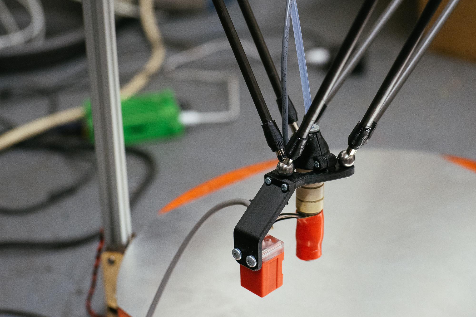
So this sensor does not have the nice cylindrical mounting ability, a small mount to the printhead is therefore needed. The sensor is small enough to fit under the printhead next to the hotend (which might produce more issues and worries but this is for a next post :) ) Bonus points; it has a detecting distance of 5mm!

To Do:


  • Construct a metal mount for the TL-Q5MC1 sensor (Unfortunately printing a mount will not be sufficient as the mount will deform ever so slightly due to the heat of the hotend, precision is key.)
  • Figure out how to save the z-offset value in marlin
  • Measure if the TL-Q5MC1 sensor can be used on 5V (making a voltage divider redundant)
  • Figure out which type of connectors to use for the wire harness (making the sensor plug an play)
  • Write a small script to send home commands to the printer and calculate average / standard deviation
  • Use the above script to test the concept of using an inductive proximity sensor as a z-probe
  • How will heat from the hotend influence the sensor measurements? if the heat has a negative influence; could this be solved by compensating the measurements in the marlin firmware using the temperature measurements from the hotend / bed? -> use the above script to measure temperature influence
  • Could this concept be used in combination with a glass bed (with metal underneath)? depends on the thickness of the glass and the detecting distance I suppose) -> do some tests with spare glass plate
  • Would it be possible to use the z-probe in conjunction with the 'normal' z-endstop? -> study ultimaker electronic scheme, I think this might be possible with a NPN type sensor.


  • Link to post
    Share on other sites

    Posted · Exploring Marlin Bed Auto Level

    I am very intrested in this Projekt and woud offer my help.

    I am fluid in Autodesk Inventor and have an close frend that coud do the metal work.

    In adition I have an Ultimaker 2 so I am abel to test how the sensor behaves with an glass plate.

    I'm not the best porgammer but if you want help...

    Best regards

    Fabian


  • Link to post
    Share on other sites

    Posted · Exploring Marlin Bed Auto Level

    Working on a https://18264080209174115072.googlegroups.com/attach/6a4574f0988edd18/DSC02438-1.jpg?part=0.1&view=1&vt=ANaJVrEbXUNc8VFLcAfkLj_zGRREZjMTBzC7YF6kU1wFt9X3SzQ7kmMM2eNhP3tEY_KaDZMlahmku-rsCGQ8Pzyxc70LtCH4tlAF7vNXv0c51HBMYNdYtlg, where bed probing is much more valuable. There are some long threads about this being done very successfully on the Delta Robot 3D Printers Google Group. Been thinking of adding it to a UM1 but haven't got around to it yet.

    Few notes to add:

    - There are very tiny 4mm and 6mm probes out there, but their sensing distance is even thinner. I have one on order and will be testing it in the next few weeks

    - Sensing distance on an aluminum plate (like a heated bed) will only be around 0.4x the rated distance of the sensor. Use either steel or aluminum foil to achieve the full sensing distance of the sensor. This is due to the way the inductive sensor detects eddy currents in the metal it is sensing.

    - On the Delta forums, there are several versions of Marlin which have various bed-probing algorithms built in. I am successfully using the one from Brad H which probes the bed 7 times in each location and takes the median value from the set. Repeatability with the probe I'm using is around 0.02mm, which seems similar to your data. From researching inductive probes, it seems like repeatability is generally given as 5% of sensing distance.... so there is a possibility that using a closer probe (ie 2mm or 1.5mm sense distance) will give better repeatability.

    (Also, if you read https://groups.google.com/forum/#!topic/deltabot/NTZUGcTKxxI, near the end, you can see some photos of the inside of a 12mm probe. I wanted to see how much smaller I could make it...)


  • Link to post
    Share on other sites

    Posted · Exploring Marlin Bed Auto Level

    Could you explain how you did the wiring, just picked up a sensor and would love to try it myself.


  • Link to post
    Share on other sites

    Posted · Exploring Marlin Bed Auto Level

    Replace the Z max endstop with the sensor. You'll have to find a pinout for your sensor to know which wire goes where.


  • Link to post
    Share on other sites

    Posted · Exploring Marlin Bed Auto Level

    I get that, since I'm assuming the switch for endstop does not have voltage, we give it power from adapter directly and connect the other two wires to the switch, or is it the opposite, that the limit switch connector has +19v power and we connect the ground to the common ground on the board.


  • Link to post
    Share on other sites

    Posted · Exploring Marlin Bed Auto Level

    2# update on our progress on the z-probe / auto-level / easy-level project

    Ok, here is a little update on the project.

    News:

    - New inductive proximity sensor still hasn't arrived :( , still waiting, I estimate it will arrive somewhere next week.

    funny-cat-post-mail-animated-gif.gif

    - The watercutter jet decided to malfunction just as I wanted to cut out the brackets for the sensor. :p Luckily the service mechanic was able to quickly get the beast up and running again. Here are some pictures of the result:

    IMG 5653IMG 5664IMG 5665IMG 5666IMG 5682IMG 5690IMG 5691IMG 5692IMG 5693IMG 5694IMG 5695IMG 5696IMG 5697IMG 5698IMG 5699IMG 5700IMG 5701IMG 5702IMG 5704


    The design of the sensor bracket is still a first version I will probably need to optimize the bracket, need to test it first :)

    I would like to thank everyone who replied to the topic, your feedback is precious, extra eyes and brains give a different perspectives on the problem / solution.


    I am very intrested in this Projekt and woud offer my help.

    I am fluid in Autodesk Inventor and have an close frend that coud do the metal work.

    In adition I have an Ultimaker 2 so I am abel to test how the sensor behaves with an glass plate.

    I'm not the best porgammer but if you want help...

    Best regards

    Fabian


    Hi Fabian, thank you for your offer. I think I will share the design file of the bracket with you so you can build your own prototype. (I think it won't fit on an ultimaker 2 head, so you might need to adjust the design) I don't have direct access to an ultimaker 2, so I am interested in your findings with your machine. Do you happen to know the thickness of the glass plate on your ultimaker?


    Working on a similar setup myself but for a Delta machine, where bed probing is much more valuable. There are some long threads about this being done very successfully on the Delta Robot 3D Printers Google Group. Been thinking of adding it to a UM1 but haven't got around to it yet.

    Few notes to add:

    - There are very tiny 4mm and 6mm probes out there, but their sensing distance is even thinner. I have one on order and will be testing it in the next few weeks

    - Sensing distance on an aluminum plate (like a heated bed) will only be around 0.4x the rated distance of the sensor. Use either steel or aluminum foil to achieve the full sensing distance of the sensor. This is due to the way the inductive sensor detects eddy currents in the metal it is sensing.

    - On the Delta forums, there are several versions of Marlin which have various bed-probing algorithms built in. I am successfully using the one from Brad H which probes the bed 7 times in each location and takes the median value from the set. Repeatability with the probe I'm using is around 0.02mm, which seems similar to your data. From researching inductive probes, it seems like repeatability is generally given as 5% of sensing distance.... so there is a possibility that using a closer probe (ie 2mm or 1.5mm sense distance) will give better repeatability.

    (Also, if you read this thread on the Delta group, near the end, you can see some photos of the inside of a 12mm probe. I wanted to see how much smaller I could make it...)


    Hi Nick, thank you for your feedback. I realize that bed probing for delta machines might be essential for Delta 3D printers. I also think that the 'regular' \ 'ultimaker-type' FDM printers might be considered 'a luxurious feature'. So why bother adding a proximity sensor to an ultimaker? Good question! The answer: I don't know (yet)!

    The bed probing feature can be found on the more high-end printers such as the uPrint series from Stratasys. It would be a logical step to translate some of the features found in high-end printers to consumer-level printers. For consumers / hobbyists it could have the following advantages:


    • 'easy-level' by providing further guidance in the process of calibrating the print-bed; 3D printing will get a bit less daunting to new users.
    • 'auto-level'; possibly no more bed calibration required; printing becomes more 'push-a-button'-printing
    • this all means: printing large objects with less hassle
    • easier to transport your printer; no need to adjust the bed after each trip

    I am very curious to what other users of ultimakers would think of this feature and how they experience it in a 'real-world' setting. I am very curious about the inside of the 12mm probe, could find any pictures on the thread you mentioned, do you have another link of it?


    Could you explain how you did the wiring, just picked up a sensor and would love to try it myself.


    Hi lohiaprateek, I will make some pictures of the wiring next week. I used a voltage divider as the sensor I had did not work on 5 volts. (first you should test if your sensor works on 5 volts as it might make the voltage divider redundant)


  • Link to post
    Share on other sites

    Posted · Exploring Marlin Bed Auto Level

    Having to run several UM:O's and 2's in a college/educational setting - manual calibration is a bit of a drain on time, auto-levelling will probably save a good hour or so a day overall.


  • Link to post
    Share on other sites

    Posted · Exploring Marlin Bed Auto Level

    update 3# on our progress on the z-probe / auto-level / easy-level project

    Another update; lot's of news:

    The new proximity sensor (TL-Q5MC1) (the little yellow boxy thingy) has finally arrived!

    IMG 5682

    I tried installing it on the bracket I had previously constructed, here is the result:

    IMG 5691

    IMG 5690

    IMG 5704

    IMG 5696

    IMG 5695


    I am not sure about the design of the bracket, I think installing it on the printhead could be easier, certainly room for improvement, the function of the bracket however is proving to be as expected.

    Because the sensor is mounted much lower on the printhead I still have the same print area as without the sensor.

    I figured out how to save the z offset value in marlin. As it happens, marlin has the eeprom-saving-option setting default at false... :p

    I tested the new sensor if it would be able to be used on 5V (making it more plug and play with the ultimaker electronics). Surprise; the sensor works on 5V! The range of the sensor does not seem to be affected by the lower voltage. When I drop the voltage to 4,7 Volts it seems that the sensor is not able to give a correct output signal. Note the led-indicator does not work using 5 Volts! :p

    IMG 5700

    IMG 5699

    IMG 5698

    IMG 5697

    Ok, here is where it gets interesting; data!

    I used a custom gcode snippet to let the printer constantly home and measure the bed at 5 different locations. In total the printer did 470 measurements, 200 of those measurements were done with the extruder and heated bed on room temperature, the second series of measurements (270) were done with the extruder and heated bed turned respectively on @ 210 and 60 degrees. The entire test procedure took around 50 minutes. I copy / pasted the entire output of the ultimaker to excel and started converting and analyzing the output. The goal is to figure out if the concept of using inductive proximity sensors for auto-bed-leveling purposes would be a good idea. I am also interested to see if the temperature of the bed and / or extruder would affect the measurements of the sensor. I've uploaded this excel file for you to look at the data and check my excell and statistical skills ;)

    Here is a summary of the data, the average of the measurement is not so interesting; the standard deviation is much more interesting:


    Locations Average of measurement StdDev of measurement Count of measurement
    A 0,954148936 0,010717243 94
    B 0,896702128 0,012127308 94
    C 1,034468085 0,009113032 94
    D 0,991595745 0,007801736 94
    E 0,99287234 0,008246516 94
    Grand Total 0,973957447 0,047294368 470

    (location A-B-C-D are the four corners of the printbed, location E is the center of the bed)

    Here is the link to: the excel file

    I'm very happy with the first results, it is certainly better than the combination of the previous sensor and PLA bracket. In the next couple of weeks I hope to see how the sensor is doing during normal printing operation, I already made some big prints with nice equally spaced brim lines!

    Here is a small video of the printer doing a calibration routine with the new sensor:

    To summarize:

    To Do:


    • Construct a metal mount for the TL-Q5MC1 sensor (Unfortunately printing a mount will not be sufficient as the mount will deform ever so slightly due to the heat of the hotend, precision is key.)
    • Figure out how to save the z-offset value in marlin - enabling eeprom save option in Marlin
    • Measure if the TL-Q5MC1 sensor can be used on 5V (making a voltage divider redundant)
    • Figure out which type of connectors to use for the wire harness (making the sensor plug an play) - jst-xh
    • Write a small script to send home commands to the printer and calculate average / standard deviation - used excel :p
    • Use the above script to test the concept of using an inductive proximity sensor as a z-probe
    • How will heat from the hotend influence the sensor measurements? if the heat has a negative influence; could this be solved by compensating the measurements in the marlin firmware using the temperature measurements from the hotend / bed? -> use the above script to measure temperature influence
    • Could this concept be used in combination with a glass bed (with metal underneath)? depends on the thickness of the glass and the detecting distance I suppose) -> still need to do some tests with spare glass plate
    • Would it be possible to use the z-probe in conjunction with the 'normal' z-endstop? -> study ultimaker electronic scheme, I think this might be possible with a NPN type sensor.


  • Link to post
    Share on other sites

    Posted · Exploring Marlin Bed Auto Level

    Bad news for the UM 2 I tried it with the CRS18-7MC1, a sensor rated for 7mm,and it does not work because the glass bed is too thik


  • Link to post
    Share on other sites

    Posted · Exploring Marlin Bed Auto Level

    I've been struggeling with a limit switch and a servo myself. Getting really tired of not getting my UM working with this. So any progress with alternative sensors I'm totally in with!

    Got a alu hotbed + 3mm glass on top.

    *sub*


  • Link to post
    Share on other sites

    Posted · Exploring Marlin Bed Auto Level

    I'm waiting for GeckoTek's spring steel build plate - I hope the proximity sensors will work on that coated steel plate. Meanwhile I updated the UBIS hotend mount design with a TL-Q5MC1 attachment: https://www.youmagine.com/designs/ubisxultimaker-printhead-with-double-sided-45-fan-tl-q5mc1-proximity-sensor-mount


  • Link to post
    Share on other sites

    Posted · Exploring Marlin Bed Auto Level

    I've been struggeling with a limit switch and a servo myself. Getting really tired of not getting my UM working with this. So any progress with alternative sensors I'm totally in with!


    Cheap servo's have low repeatability. So that will give you problems. It would be better to use a solenoid.

    Another possible method is using the bed springs as switch: http://ei8htohms.tinyparts.net/?p=1111


  • Link to post
    Share on other sites

    Posted · Exploring Marlin Bed Auto Level

    This forum is closed and I haven't been able to find any other info on this approach, but it looks pretty interesting. Uses just one DC motor to mechanically level the bed, no more software compensation.

    https://groups.google.com/forum/#!topic/makerbot/R3lSfnCz5W4


  • Link to post
    Share on other sites

    Posted · Exploring Marlin Bed Auto Level

    Bad news for the UM 2 I tried it with the CRS18-7MC1, a sensor rated for 7mm,and it does not work because the glass bed is too thik


    Have you tried putting a thin piece of steel (not alu.) between the alu. heated bed and the glass plate? Something like a metal scraper lying around somewhere.

    The sensing distance is based upon sensing steel instead of aluminum, the latter greatly reduces the sensing distance.


  • Link to post
    Share on other sites

    Posted · Exploring Marlin Bed Auto Level

    I think a mechanical end stop switch sensor gives the most interesting options if it's accurate enough, more so than one that only detects metal. In theory you could resume some types of partial print by first calibrating the bed through the corners, then moving the Z axis to the bottom limit, center the head and move the Z upwards until the plastic part hits the calibration switch, probably repeat the calibration a couple times to get an average and then start skipping gcode until you get to the layer that corresponds to the measured Z height and start printing. It won't be perfect since the printer will most likely have rehomed all three axes so they have slight offsets, but it might be good enough.

    I gotta say that after all the upgrades the ultimaker is so reliable it doesn't really need a resume feature anyway, but it would sure be neat for those times when you ran out of plastic, or lost power, or some other accident happened :)

    Perhaps you could even glue flat plastic cases, books or whatever to your print bed, calibrate against them and engrave them with plastic ;)


  • Link to post
    Share on other sites

    Posted · Exploring Marlin Bed Auto Level

    but it would sure be neat for those times when you ran out of plastic


    It would be better to have a "pause" switch on the feeder for this.

    And if you want to sense the bed in a "non contact" way. A analogue capacitive sensor seems to be able to detect the bed trough the glass just fine. But might be tough to calibrate.


  • Link to post
    Share on other sites

    Posted · Exploring Marlin Bed Auto Level

    I suppose it would be easier to add pressure sensors instead of the leveling springs, so that the print head pressing on the glass would immediately register. You would not need the spring, since your are leveling to whatever plane the glass is currently at. Perhaps if I get my printer repaired I could give it try (I have several pressure sensors from small weight scales).


  • Link to post
    Share on other sites

    Posted · Exploring Marlin Bed Auto Level

    I made some tests with my Fotek PS-15N sensor. The results are excellent.

    The sensor detects the 4mm aluminium plate with more than 4mm gap over the 3.2mm borosilicate.

    http://youtu.be/Ntz-r8ECLTwhttp://youtu.be/Ntz-r8ECLTw


  • Link to post
    Share on other sites

    Posted · Exploring Marlin Bed Auto Level

    Hi there to all, a manual or instructions for wiring and programming ??

    Greetings Markus


  • Link to post
    Share on other sites

    Posted · Exploring Marlin Bed Auto Level

    Hi there to all, a manual or instructions for wiring and programming ??

    Greetings Markus


    Hi Markus, most of the conductive sensors output a 12 volt signal while the Arduino wants 5 volt. This topic explain how to use a resistor divider to address this problem: http://electronics.stackexchange.com/questions/43498/how-can-i-use-a-12-v-input-on-a-digital-arduino-pin


  • Link to post
    Share on other sites

    Posted · Exploring Marlin Bed Auto Level

    ok but I was thinking more of the marlin firmware. How it fits or how they adapt and what we need to change. In addition to find a good manual is difficult.


  • Link to post
    Share on other sites

    Create an account or sign in to comment

    You need to be a member in order to leave a comment

    Create an account

    Sign up for a new account in our community. It's easy!

    Register a new account

    Sign in

    Already have an account? Sign in here.

    Sign In Now
    • Our picks

      • UltiMaker Cura 5.7 stable released
        Cura 5.7 is here and it brings a handy new workflow improvement when using Thingiverse and Cura together, as well as additional capabilities for Method series printers, and a powerful way of sharing print settings using new printer-agnostic project files! Read on to find out about all of these improvements and more. 
         
          • Like
        • 18 replies
      • S-Line Firmware 8.3.0 was released Nov. 20th on the "Latest" firmware branch.
        (Sorry, was out of office when this released)

        This update is for...
        All UltiMaker S series  
        New features
         
        Temperature status. During print preparation, the temperatures of the print cores and build plate will be shown on the display. This gives a better indication of the progress and remaining wait time. Save log files in paused state. It is now possible to save the printer's log files to USB if the currently active print job is paused. Previously, the Dump logs to USB option was only enabled if the printer was in idle state. Confirm print removal via Digital Factory. If the printer is connected to the Digital Factory, it is now possible to confirm the removal of a previous print job via the Digital Factory interface. This is useful in situations where the build plate is clear, but the operator forgot to select Confirm removal on the printer’s display. Visit this page for more information about this feature.
          • Like
        • 0 replies
    ×
    ×
    • Create New...