


muttstang
-
Posts
51 -
Joined
-
Last visited
Content Type
Forums
Events
3D Prints
Posts posted by muttstang
-
-
Not much for pictures really. I print a lot of concept prototypes. Latch mechanisms, valve assemblies (lots and lots of valves) for high altitude lighter then air systems.
-
Or just increase the gear reduction some more depending on if the motor is capable of the RPM's at whatever the load ends up being. The bigger the gear reduction, the more that the relative rotation will be minimized. You can pretty easily get some 64 pitch worm gears and see a 60:1 reduction without a lot of size. You will likely have to buy the gears as the teeth would be getting a bit small for printing, especially with the higher friction loss that you get from worm gears
-
you could change the bearing to a grooved bearing design to spread out the contact area with the filament.
-
Here's a thought. What if the motor was mounted on a carriage that aligns itself with some form of telescoping rod with the extruder head? That way there is no relative rotation induced in the flexible shaft. Implementation may be tricky but I think this would get rid of that error.
-
Has anyone tried using a push to connect type of tube on an extruder upgrade by chance?
I have a design and left provisions for a 1/8" NPT fitting and am trying to figure if a push to connect will work instead of a compression type of fitting.
A push to connect fitting will generally allow the tube to be pulled out slightly so I don't know if this would cause issues. A compression fitting will be more of a rigid connection.
-
What would be nice would be to have a 5 point for flattening the bed then 3 point below it for leveling. Keep them separate to make it work.
-
The bigger drive wheel has more contact area. Plus it is a straight groove and not a knurl so it has more bite
-
You could do a single drive with a gear reduction while using a knurling tool head.
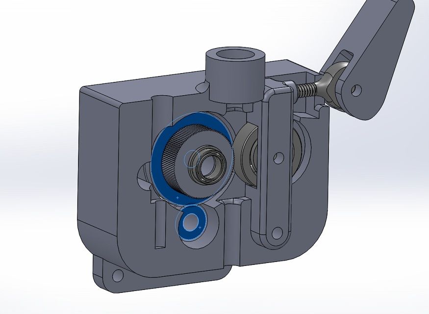
I'm pressing these onto roll pins.
There is a tube so that you can run a cleaning brush in there and clean off the feeder wheel.
the tensioning arm can be released with a simple over-center arm. Not much for adjustment on the spring of the tensioning arm at this point. I might have something in mind for it though.
The blue wheels are gears, the small one being pressed onto the stepper motor.
I believe the gear reduction is 6.35:1
.375" gear to 1" gear, down to .75" knurl wheel divided by 8mm/25.4 (od of original knurled wheel)
-
Welp, MB approved the return of the Z18, though they are looking to charge the 10% restock fee on a printer that never worked right in the first place.
The company is going to fight that a bit.
Either the engineers at makerbot weren't admitting to the problems they were having, or else the exec's there ignored the engineers' advice and went to market with a defective product.
-
I might skip the 3 knurling wheels. That requires some pretty complex gearing and I'd rather keep it simple. I'm going to try just a gear reduction to get more power out of the motor and use a larger knurling tool as the drive wheel.
Though the flex shaft idea has me interested. I might have to pick up a nice flex shaft from mcmaster and do some of my own testing
-
I use solidworks because work is paying for it. I wouldn't pay that much for the software if it was for just me. it is fortunately on a laptop so I can take it home and work on other stuff on the side
-
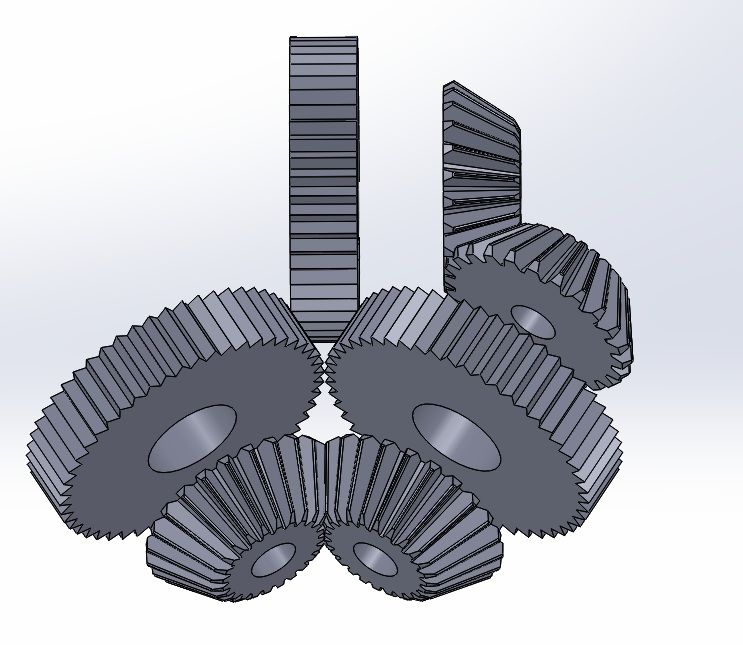
Could you use a set of 45 degree gears to minimize the need for lubrication? Probably would need an extra gear reduction to get 40:1 though.
might be a pick your poising kind of thing there.
-
Some more wiring in place. wire ties are loose and wires are not in tight yet as I still have to run my limit switches. I haven't quite figured out the brackets for that yet
-
that depends on if you can adjust the rpm on the stepper and where the peak torque of the stepper is. I'm guessing that the peak torque on the stepper is at a higher RPM then it currently operates. So you would gain some power by spinning the stepper faster to get the proper rate of rotation on the extruder. Now if you are direct driving those wheels then you will have to spin the stepper even more slowly and will lose torque from the larger diameter as well. I wouldn't want to direct drive the bigger wheel. Direct drive may be simpler and make for lower part count, but it does not allow the stepper to operate at it's most efficient speeds.
-
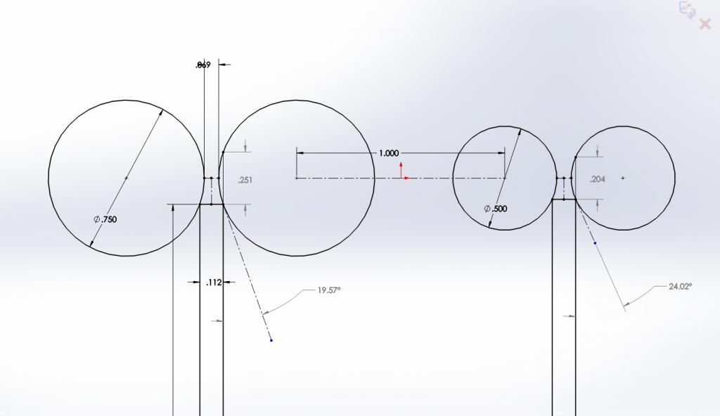
I still think just going to a pair of driven wheels of a larger diameter will make a huge difference.
A quick sketch shows it has a lower angle for the filament to enter so loading would be easier. There is also 20% more contact area on each side. To keep the stepper rotating at the same rate there would have to be a matching gear reduction prior to hitting the drive sprockets.
-
You should still be able to spring load something like this, the gears would retract to load filament and if you size it right then you can get this thing to grab the filament pretty darn hard.
-
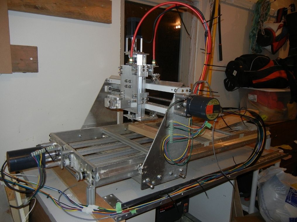
Here's another project I've been working on...
First time hooked up to the computer.
-
yeah. driving both wheels would likely help a lot. or just larger diameter wheels to get a larger contact patch.
-
solidworks here. thats what we have at work. It was up to me to choose and that is what I was accustomed to working with. very easy to use with a lot of options. I'd like to get a bit better at surfacing but dont have to use it much at work. I've modelled up some carved top guitars that look pretty good though. built 3 of them now.
-
I ordered the UM2 today and MB is sending a packing kit for the Z18

I did figure out that the thermocouple on my UP! was bad so I ordered a new one of those. I should be up to 2 printers soon
I have a novel idea for a new feeder that I'm planning to put together using 3 straight knurling tools.
-
what about a metal sleeve around the PTFE to help it maintain it's dimensions when hot. Don't run it all of the way down to the nozzle end so that there is a bit of thermal seperation.
-
One thought on belt drives. The belt really only grips the filament where the wheels sit. So you could get the same effect using rubber wheels as you get by using a belt.
-
Is there any feed rate setting in Cura that can be used to compensate for a different diameter on the extruder wheel? I think just a larger extruder wheel would make a big difference. Especially if it is a straight groove instead of the knurl.
-
Could someone use a knurling tool head? something like mcmaster part 3330A32?
you could potentially use 2 of these (one on each side of the filament) spring loaded together and then linked with a single gear attached to the drive motor. That way you can set up the gear ratio to match the original diameter of the knurled piece on the stepper?
I have something in mind but I have to sketch it out.


Examples of truly practical/useful prints?
in Coffee corner
Posted
I think the coolest thing I printed out was a valve that runs on a cam drive instead of screw drive. It is for high altitude (as in 70,000 ft) as our power requirements are very strict up there. Plus it has to operated down to -80C