


aviphysics
-
Posts
571 -
Joined
-
Last visited
Content Type
Forums
Events
3D Prints
Posts posted by aviphysics
-
-
There is a lot of work to do before production so I don't know for sure when that may be.
A question for those who may be interested. Would you rather?
A: Receive all hardware and print the gearbox, motor mount and motor adapter yourself ($100-150)?
B: Receive all hardware and 3D printed gearbox, motor mount and motor adapter ($130-180)
C: Receive all hardware and machined aluminum gearbox, motor mount and motor adapter ($200-250)
Prices are rough estimates, just trying to get an idea what people would want.
I think my budget would top out at about $130. Also, while I will definitely need a good extruder for large prints in the next year, I won't be needing one right away.
One question. What is the compatible range of filament sizes?
-
1) The print head is lighter, because there isn't a fan on it.
2) The print head is smaller, because there isn't a fan on it.
3) Maybe this is just me, but I found my overhangs with the crossflow fan were substantially better than the results I was getting with the UMO stock fan and cowl. I think it just provides a lot better cooling of the layer, as it is blowing more air over a larger area.
BTW,
I have also started using a crossflow fan for cooling the stepper motor on my Nema 8 Direct Drive extruder. Works like a charm.
Oke so the are worth it but the are really expensive and i can`t find the in the right size. Or are we not on the same page?!
I got some used ones off of ebay.
-
Preview of my upcoming more compact Nema 8 design. I am still working out some interference issues with the Nema 8 mounting screws.


-
 1
1
-
-
Well, everything I printed the last 18 months was with the crossflow fan. On the old forum there were a lot of pictures ...
Uploaded a few again.
Well the look really nice but how that looks a crossflow fan, and is this better than a normale fan?
1) The print head is lighter, because there isn't a fan on it.
2) The print head is smaller, because there isn't a fan on it.
3) Maybe this is just me, but I found my overhangs with the crossflow fan were substantially better than the results I was getting with the UMO stock fan and cowl. I think it just provides a lot better cooling of the layer, as it is blowing more air over a larger area.
BTW,
I have also started using a crossflow fan for cooling the stepper motor on my Nema 8 Direct Drive extruder. Works like a charm.
-
1
-
-
Posted my final design for this version on Youmagine.
https://www.youmagine.com/designs/nema-8-worm-gear-print-head-redux-for-foehnsturm-modular-printhead

Also working on a more substantially different version with lower center of mass.
-
Look up "Crossflow Fan". These fans produce a sheet of air, so you can have one on the side of the printer blowing across the entire top of your print.
Well the are a kind of big

But they don't have to move with the hot end, so weight isn't such a big deal.
-
rev3, trading 15 mn of height for 10 mm width
I really like the design,

But i only miss a extra fan for cooling for the print
Look up "Crossflow Fan". These fans produce a sheet of air, so you can have one on the side of the printer blowing across the entire top of your print.
-
2
-
-
One thing I didn't expect with the Nema 8 design is that it is way quieter than the UMO stock extruder. I am guessing that is due to the increase in step frequency and decoupling from the wooden frame.
-
... some progress. Learned how to print reliable with PLA HT and finished the first dock.


How does the pancake stepper compare to the Nema 8 motor?
-
I would be interested. I just got my Nema 8 extruder up and running. You can find the details in your direct drive extruder thread.
Right now my gear box is substantially heavier, primarily due to the much larger worm gear.
Looks like you also moved to 5 mm rod for the gear box axle.
-
Had some free time this week so I finally got my version assembled.
The overall design is the same, but I remodeled the body from scratch.
Main Differences
- changed hot end mount to UBIS
- slightly increased angle of motor mount, to give more room for cooling
- enlarged gear box to accommodate a wider variety of worm gears.
- increased gear box shaft to 5 mm. Bearings are still 10 mm OD
Though the motor is rated for 0.8A, I am getting good results from 0.6A. Currently running 1/4 steps at 1553 steps/mm.
The frame weighs just a tiny bit more than the original design, but the worm gear I am using in this design is a lot heavier and the thicker shaft also adds some weight, though I thought the 3mm shaft had too much flex to it. Maybe the 5 mm shaft could be drilled out, to reduce weight. Same for the gear.
The hair bands don't actually do anything, they are just there to hold the feed tube when the filament is removed.
I need to print one more version of the body that had a holder for the feed tube. After that and some more testing will post on youmagine.


-
1
- changed hot end mount to UBIS
-
Yes and no. Yes, x and y axis are important but (no) don't underestimate the extruder motor(s). Just unhook it during a print and you will hear the difference.
Just decoupling the feeder from the chassis makes a huge difference. IME, the silentstep stick did not make a huge difference in the sound of retractions, but decoupling the feeder from the chassis did.
It was expected that this wouldn't fix the E-Motor noise. Because the E-Motor moves very fast during retraction, Marlin sends two step pulses at a time so the interrupt handler doesn't get called more often than the poor little 8bit AVR can handle. So the output is: "step,step,pause ,step,step,pause, ...". Of course it doesn't help to smooth in-between steps when the steps themselves are irregular. Don't take my word for it, look at the code (stepper.cpp).
Yuck. Seems like they should have just cut the microsteps to 1/8th and done a single pulse.
-
Well, I posted the bug reports. I briefly looked for similar issues reported, but didn't see them.
They just seem so obvious and problematic, that I have a hard time believing that the devs haven't noticed, unless it is somehow specific to my installation.
-
I have just felt like I am in a constant battle with Cura 15.06 (Currently on 15.06.03). The biggest issue is that it will often fail to recalculate after adjusting a parameter, but there is lots of other buggy weirdness; like how when you grab a part to move it, the Cura GUI with throw it way off to one side.
I would very much like to go back to 15.02.01, until things get sorted out, but the new Slicer does seem to make a higher quality prints. Would it be possible to use the old GUI with the new slicer?
-
I also noticed the discoloration of the black coating, but I was attributing it to some of the bronze wearing off on the rods. The same thing probably happens with the standard rods, but it isn't as obvious on the shiny chrome or steal.
Either way, they don't stay that pretty mat black very long.
-
1
-
-
I just finished glueing the neodymium to the new carbonfil carriage and head holder.

The thing I didn't account for its that this filament expands a bit more (I think) so now the linear bearings are a hard to push in. It's a good idea to put them on the freezer befor fitting them? I put them in a claed bad to avoid humidity but I'm not sure. Good or bad idea?
Alternatively, you could use a reemer to make them the perfect size.
-
I am using an UMO with a 0.5 mm nozzle and trying to slice with the Cura 15.06.03.
I created a custom JSON file with the nozzle size set to 0.5 mm
"machine_nozzle_size": { "default": 0.5 },The problem is that Cura still highlights "Layer Height" in orange when I try to set it above 0.3 mm.
Is this the intended behavior? Did I miss a step? Is there a work around?
-
Just got one of these for changing our nozzles. It works beautifully.

-
foehnstrum is giving a talk in my home town about his tool changer! Check it out:
http://www.fab11.org/workshops/ops304/
Maybe I'll crash it and ask some difficult questions?!
So far :(. @foehnstrum, you are always welcome on the west coast too.
-
I'm having issues with Colorfabb PLA/PHA too. What do you guys think?
check the link below please:
https://ultimaker.com/en/community/view/16428-printing-issue-under-extrusion

I am having similar results with the silver. I had to push the temperature up to 228 C to resolve them; but, I am printing with a 0.2 mm tip on a Merlin hotend.
-
There does not seem to be a turbulence problem between the two fans. The air for cooling the hot end would be directed into the room. The point of using two is that the top fan can draw cool air from the room, while the bottom fan recirculates air around the heated bed.
I am not sure if it matters if the top and bottom fans are running at different speeds.
-
Exactly! If I would have to design a printer I would start with your idea. It's the most straightforward approach to provide an optimum thermal situation.
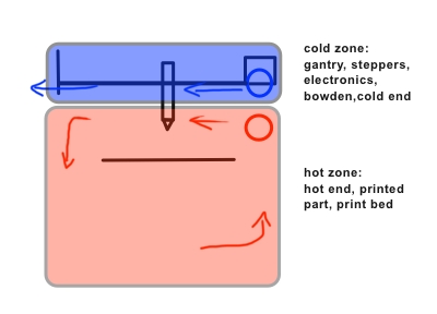
Has anyone rotated their printer 180 degrees so the device is upside down? I can see a few problems with this like bridging creating hanging bits that would hit the printer head. I ask because in some regards I think this would be the easiest way to retain the heat in the printer in the correct areas of the printer. Keeping cool air at the "bottom" of the printer separated from the hot air at the "top" as a function of the differences in their densities. Probably not worth the hassle though, but an interesting thought.
Anyone tried this yet? I had originally bought a fan off e-bay that didn't work at first, so I ordered another. I just got the first fan working again, so now I have two mostly identical crossflow fans.
-
For smaller fans, an RC low pass filter works pretty well. I used a 5 ohm resistor and picked a ceramic capacitor to filter down to 3kHz.
It kills some of your top end voltage though and it doesn't work as well with the electronics in my non-PWM crossflow fan.
-
I had a quick look at misumi already but found the options a bit overwelming
Very true. TBH, I didn't do any calculations, to some extent it's a shot in the dark. Just went for the long blocks for less play. An axis with two parallel rails should always be fine. With the one rail axis, I'll have to see. And for the other options: I tried to choose the cheapest ...
When I looked at rail systems for my CNC many years ago, my impression was that one really needs a pair to avoid any significant wiggle. It just doesn't take much angular freedom at the rail to cause problems, when the tool extends out several cm. Perhaps designing the tool holder to keep the hot end as close to the axis as possible would help, but than your center of mass (and/or Bowden) will be way off axis and able to apply a substantial torque.
A lightweight second rail could be added opposite the tool changer to help reduce the degrees of freedom. This would be like the very small bearing used at end of the non-load bearing side of a rotating shaft, in order to offset the load. In thise case, the rail could be oriented to maximize its vertical rigidity.


Gear Extruder - Anyone interested?
in Third party products & modifications
Posted
Hi Martin,
That's a great looking extruder. It looks like the drive gears share a similar design to the MK8 RepRap drive gear, which I have found gives really good grip without deforming the filament very much.
On the 3mm variant, what do you feel is the compatible range of filament sizes? Also, how hard is it to convert the 3mm variant to 1.75mm and back?