


conny_g
-
Posts
802 -
Joined
-
Last visited
-
Days Won
12
Content Type
Forums
Events
3D Prints
Posts posted by conny_g
-
-
Here are zoom photos of 2016 where I started to do laser exposure of PCBs using the mechanics of the UM2.
You can see the steps "paused" by the stepper.
I think I exposed with 1016dpi here which is half the technical resolution of the steppers, so you see the pause every 8th step.
Now - unfortunately I haven't made a photo of that - the effect is gone - I did the solder fix to connect the ROSC pin to ground.

-
 1
1
-
-
7 hours ago, lars86 said:
I'm just curious how those voltage regulator board would handle a PWM signal (for the print fans).
Taking a random small one like this:
https://eckstein-shop.de/Mini-DC-DC-Step-down-Spannungsregler-MP1584EN-Buck-Power-Module-Outout-08-20V-3A-?curr=EUR&gclid=EAIaIQobChMIqr390P722AIVZirTCh3CswVyEAQYASABEgK3PPD_BwEIt has a switching frequency of about 1 Mhz, while the board has a PWM frequency of < 38 kHz. That would be ok.
And the IC on that step down board has a startup / shutdown time of "a few ms" and that kills it, it can't keep pace with any PWM that's much higher than 100 Hz.
I would not feel comfortable using a step-down powered by a PWM signal.
What you could do is create a small circuit powered by the step-down (19v > 12V, taking the 19V from somewhere else on the board) using the original fan PWM as input to switch a MOSFET that pulses the 12V output of the step-down. That's a really small circuit out of a MOSFET and a resistor. For 0.1A you could even use a normal small npn transistor (BC337 or something). -
Do you want to have the fan PWM controlled or would it be ok if it simply runs at 12V and that's it?
-
7 minutes ago, lars86 said:
Thanks for the reply @conny_g
I'm pretty sure that VCC/2 is 19v on the UMO and that they just found a 12v fan that "lives" at 19v.
Oops, you are right. On the top left you see that VCC/2 is 19V.
-
13 minutes ago, bob-hepple said:
I find this ironic, I posted that I had printed these parts out and there was no Gap (conn g) implied my prints were under extruded? and low and behold the STL files are wrong. I botched my print head to make the gap, exactly because there was no gap, and have shelved my conversion, because I knew the files were suspect. I am grossly disappointed.

I think in most cases the head still works as designed, if the magnets touch or are very near (0.1-0.3mm) so their force is maximal.I am using the new head without gap currently and I cannot find any issues with it so far.
-
35 minutes ago, foehnsturm said:
Hmm, there still should be a small gap (but it should work anyway). Will have to measure the step/stl.
Up to my recent experience with the corexy magnet tool changer parts it's quite easy to insert the magnets deeper than intended with a little more force applied. The bottom of the pockets in the print head actually isn't that strong (printed by bridging).
I used quite some force as I wanted to make absolutely sure to not have the magnets twisted again as last time.... :-)
The head was sticking "ok", but not strong in the first setup due to that. And I have the suspicion that this caused inaccuracies in the print of some 0.1-0.2mm. -
Researched a bit and found:
The Ultimaker 1.5.7 board bases on Arduino Mega plus a Ultimaker shield:
http://reprap.org/wiki/Ultimaker's_v1.5.7_PCBThere is only 1 fan connector:
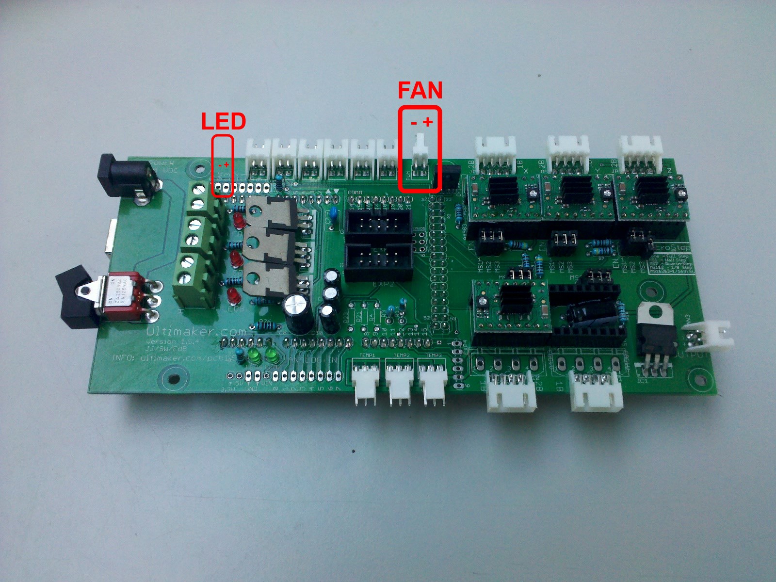
According to this schematic: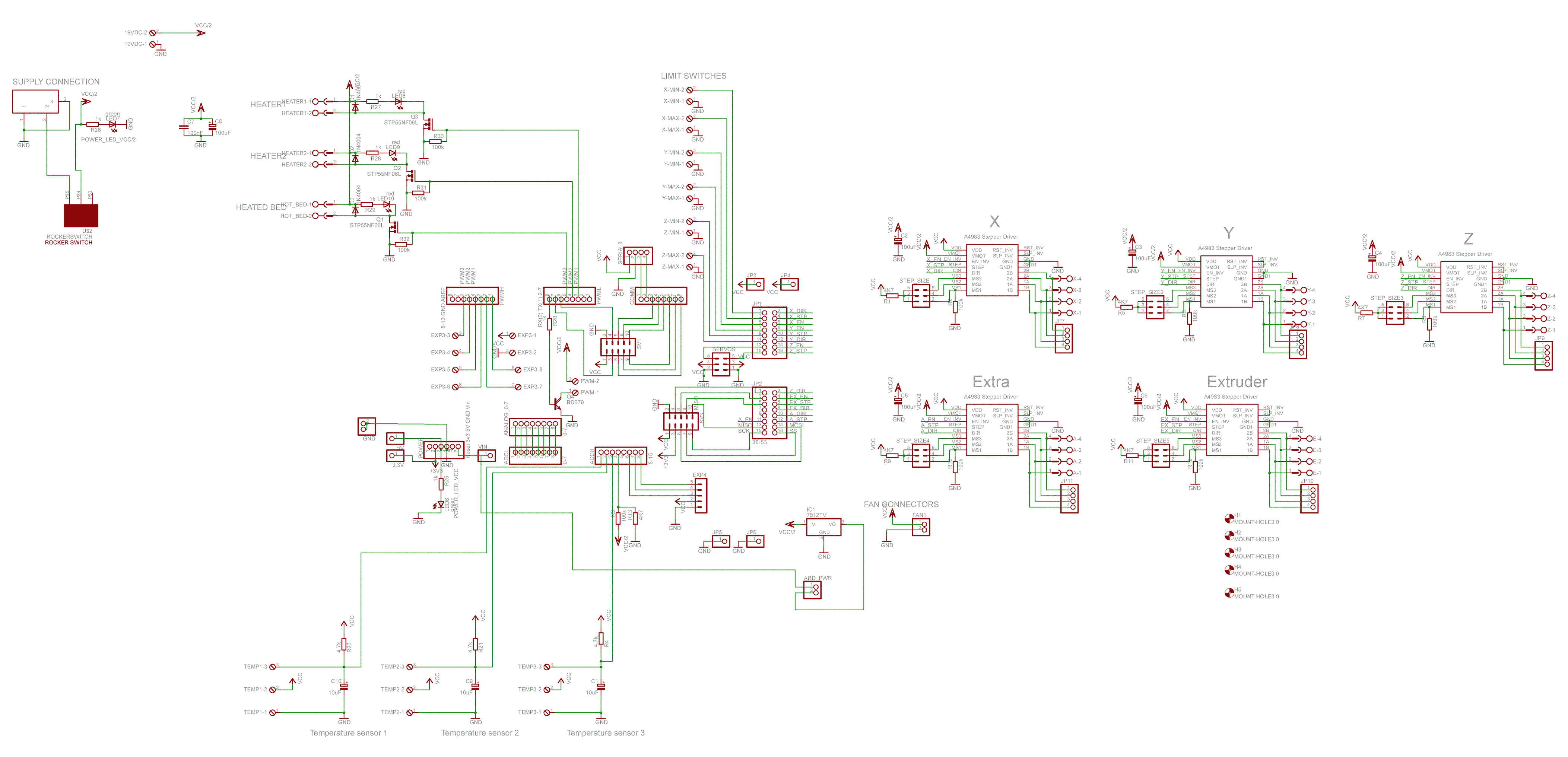
and this offer:
https://www.fablabfactory.com/products/ultimaker-fans?variant=50721821907it uses VCC/2 = 12V.
It is driven off the PWML connector that also serves the heaters.
And in the above schematic you see that a BD679 darlington transistor drives this:
http://www.onsemi.com/pub/Collateral/BD675-D.PDF
The mentioned datasheet says 4A. Which probably refers to the derating diagram which allows 10W of dissipation at 120C.
As you are planning for a 12V fan, you have an output serving that and 0.1A should not be a problem at all.
Other than that, maybe this is what you are looking for: -
@foehnsturm
I assembled two heads now - redid the previous one to improve force / accuracy (magnets were not it completely straight) and made a new one for the second printer - and there is no gap between head and coupling for me.
It seem that the 3D model of the coupling changed, it's now 0.25mm thicker than the old one. Compared my old coupling with the new one with a caliper.I don't think that's an issue (the magnets seem to still touch and have enough force), but just to let you know and to check if this known and/or if it was intended.

-
Extrudr Green-Tec White.
-
Everything ready to convert my 2nd printer to Mark 2.


-
3
-
-
Have a look at the Octoprint API documentation:
http://docs.octoprint.org/en/master/api/index.html
You can retrieve info about the running job (if submitted from Octoprint)
http://docs.octoprint.org/en/master/api/job.html#retrieve-information-about-the-current-jobI think you can even print jobs from the SD from Octoprint.
You can do all the things Octoprint does regarding the printer status yourself, if you want. It is simply processing serial output that comes from the printer via USB or uses G-code commands to query the status.
But Octoprint does all this already and much more and gives you a REST API for that, which is easier than to deal with the G-code commands and all the serial communication stuff. -
The other printer had a worn Teflon coupler and some burnt crap in the steel isolator....
-
Where can I buy the Mark2 extension board again....?
Ah, I found it... IdeaTo3D in Belgium. I actually now ordered most of the parts (and the Mark expansion board kit) at Didier Klein's shop. ;-)
-
This one, btw:
https://de.aliexpress.com/item/3D-Prnter-Power-For-Ultimaker-2-UM2-Extended-Power-Supply-3D-Printer-Parts-24V-15A-Top/32707066340.html
Works for one year without issues now.-
1
-
-
14 minutes ago, ultiarjan said:
Print head
- Olsson block - don’t care, will covert to 3D Solex Matchless V3. Is it possible to mod the UM2 head with that? Yes, though I'm not sure there will be any benefit vs a standard Olsson block
- Stronger heater - already ordered a set of 50W, I wonder if 2x 50W will get you into trouble with the available power, power management is an issue for some people already
3D Solex Matchless V3:Yes, I am using them on my two printers, one Mark 2 and one UM2+ (upgraded from UM2) and they are "good", but not as "magic" as promised. I think the temperatures are slightly lower than before, but I can't really print very much faster than before. Maybe 10-20%. They are slightly easier to clean with the chrome plating. So they are "good", but not "magic". Now that I am there I'll stay there and have only 1 type of nozzles.
Stronger heater: On my Mark 2 I am using a power supply that provides some 100W more than the original Ultimaker one, it has 15A (360W). So that should be ok. Haven't had any power outages any more since then.
-
1
-
Ok, so in summary these are the changes of the extrusion upgrade:
- New feeder (I use Bondtechs anyway)
- improved fan shroud (will buy one)- fixed coupler instead of spring in the hotend (will print one)
- stronger heater 35W vs. 25W (ordered 3D Solex 50W)
- Olsson block (using 3D Solex Matchless V3)
So I am covered, there is no changes I cannot cover with the old hotend, so I can reuse it without restrictions.
Happy! -
-
Ah, there it is!!
Extrusion upgrade kit:
There's wires for:- heater
- temp
- fan hotend (blue / orange)- fan model (green / yellow)

And my "old" UM2 hotend has the following cables:
- heater
- temp
- J34 / hotend fand (blue / orange)
- "fan" (brown/red)
- fan PWM (green/yellow)

Where the "fan PWM" went to J14 (next to the LED PWM port) and the "fan" connector went to that J20 19-24V Fan port (right side)
On the hotend there's just red/black wires at the fans, so the "magic" happens in the cable hose.
Let me see. The green/yellow are putting the two model fans in series as they do in the UM2+ hotend.
INCREDIBLE!! The brown/red is not connected, I could just pull it out of the hose!!
So the answer to my question is: the fans are identical, the wiring is identical, there is just a unused "phantom" cable in the UM2 hotend :-)
-
29 minutes ago, nilrog said:
Afaik the fans are the same...or possibly a slightly better model...the BOM on GitHub doesn't specify which model they use.
The cabling is the same though...because you can order the extrusion upgrade for the UM2 which is a drop-in replacement for the old UM2 printhead. You just swap out the old one with cables and put the new one in place with it's cables.
And that's why I thought they are different, I have used a extrusion upgrade and the fan wiring was different as far as I remember. I could check the UM2 drivetrain and compare to photos of the extrusion upgrade.
Just spend some time googling for images / descriptions of cabling UM2 vs. UM2+, unfortunately not too much to be found, especially nothing about UM2. -
23 hours ago, conny_g said:
[....]
Fans and cabling:
- one was a different hotend Fan and how it’s connected (UM2 always on, UM2+ controlled by firmware?) ? Is it the same fan?
- The fan shroud is optimized on the 2+. Could print one.
- And wasn’t there something with the model fans, too? Are they same or different?
The questions about the hotend are answered, thank you!What about my questions about the fan setup UM2 vs. UM2+?
I found that I can order the fan shroud if I wanted the identical one, but I am not sure about the fans and their cabling. -
4 hours ago, nilrog said:
Yes, I know. I think I'll try the printed one before ordering it as a replacement part.
-
26 minutes ago, rajilpahuja said:
EVERYTHING IS POSSIBLE, BUT ITS REALLY UPTO YOU, AND WHAT KIND OF QUALITY IS ACCEPTABLE, FOR ME PERSONALLY FINE DETAILS MATTER, BUT MAYBE THOSE SAME DETAILS DON'T MATTER WITH YOU, SO YOU CAN TRY THIS AS WELL PERHAPS YOU MIGHT GET GOOD RESULTS AND IF YOU DO PLEASE SHARE WITH US TOO
")
Why are you yelling at me?
https://newrepublic.com/article/117390/netiquette-capitalization-how-caps-became-code-yelling
-
2
-
-
It seems printing is possible with that spring replacement spacer.
https://www.youmagine.com/designs/um2-adjustable-spring-replacement
https://www.youmagine.com/designs/um2-spring-replacement-for-i2k
https://www.youmagine.com/designs/ultimaker-2-spring-replacement
https://www.youmagine.com/designs/um2-spring-replacement
-
21 minutes ago, rajilpahuja said:
The filament path is more rigid and straight, which gives you beautiful and error free prints, with spring it has the space for movement.
Ok, you mean the print head top and bottom plate are not only connected with the alu grid next to the hotend fan but also with alu ring + ptfe + steel Isolator as a static element.
That makes sense. Can’t find it as replacement part separately, though.


")
Ultimaker Mark2 - The Smart Dual-Extrusion Upgrade
in Third party products & modifications
Posted
Do you have a register of the users? I remember you once planned to do a world map where how many built Mark2...?