


coseng
-
Posts
49 -
Joined
-
Last visited
Content Type
Forums
Events
3D Prints
Posts posted by coseng
-
-
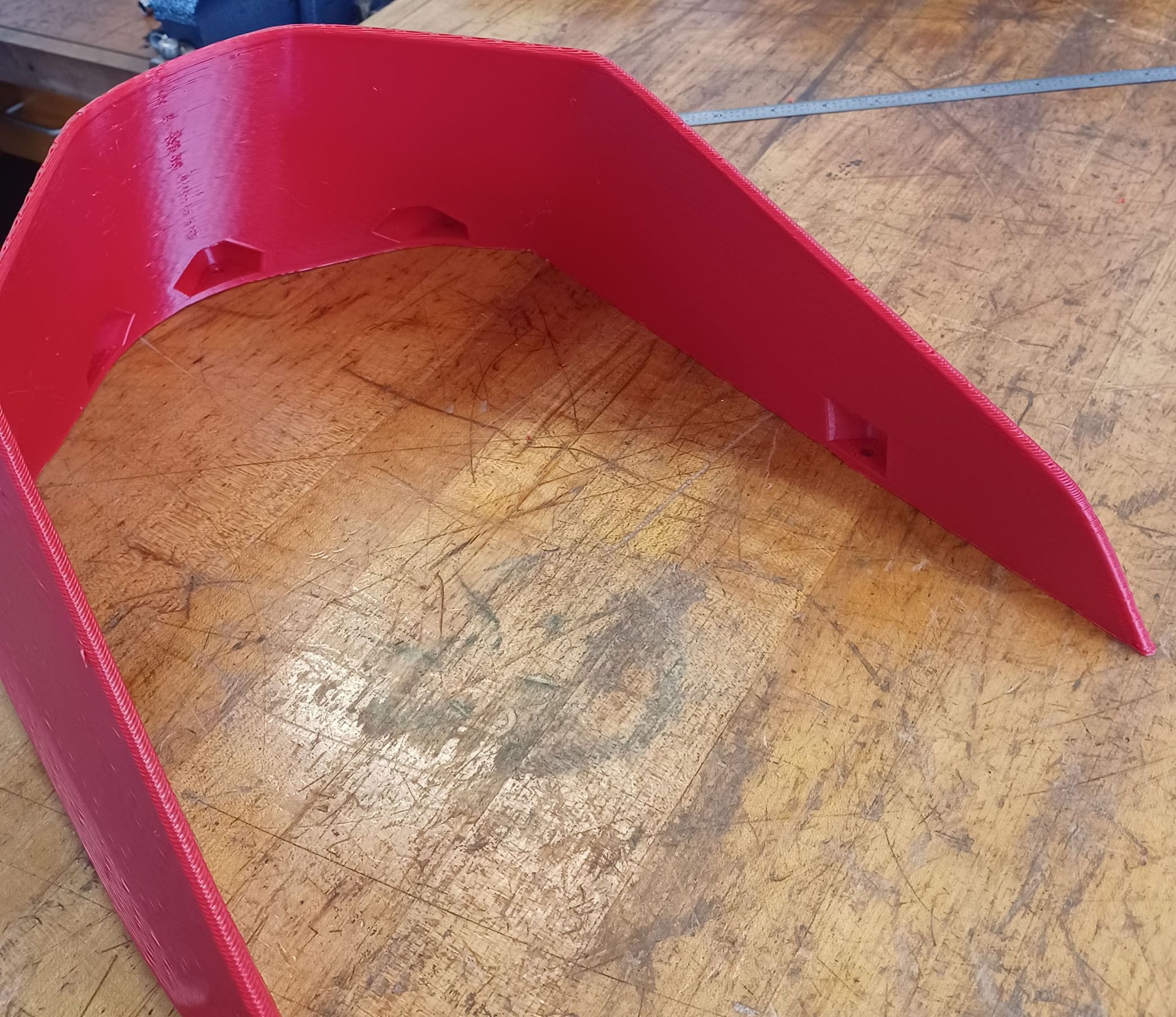
The tank finished successfully and is a mostly a really good print.


The only issues are on the horizontalish areas where I think another inner wall or skin layer is needed. I'm not sure what the setting for this type of geometry is.


I was pleasantly surprised with how easily the standard supports broke off and the finish under them is still halfway decent. I used the standard supports with I think too fine of a density. Choosing the tree suppports (without changing any of the settings) increased print time from 11 to 13 hrs so I went back. I think a bottom skin is also needed. Those surfaces are completely internal so does not really matter but it is nice to have 100% nice parts.

I then went tall and tried the subframe, but with minimal supports, which ended up being a mistake.

One out of two legs printed fine, so this could still be used as a mockup and I am letting it finish. On hindsight, I was suspicious of the small islands with nothing joining them to the main brim but decided to run it anyway. I'll add some supports there and tie them to the main support structure before rerunning it. Time to learn how to do that! -
That's some nozzle! The clearpath tech was tuning the XY motors on my setup and they rapid smoothly at 1200mm/sec, but at those speeds the bellows is a noisy mess! I limit it to 600mm/sec and it still seems like an instant move.
-
>>I think if the "squareness" of the printer is off it won't be by much or your previous parts would have shown an indication.
Hopefully you are right! Going from 300mm print height to 900mm so we'll find out.
>>Are you confident in the sending units/thermistors calibration? Is it possible they aren't just measuring the device they are supposed to monitor but picking up some residual heat from another source
The temp sensor readings agree pretty closely with my handheld IR temp gun. There is some cross talk, the chamber heater hot air exit has to be impinging on the bed somewhat. The bed sensor is embedded in a 50mm long drilled hole from one edge, so not exposed to air. I was just surprised at the seemingly small amount of heat needed to keep the unit at temperature. Once past warmup, the nozzle heater is mostly on and the chamber heater is mostly off, and the bed heater is usually never on.
That's a nice unit! What is your throughput with the pellet feeder? I'm getting roughly 200g/hr with my wall print speeds of 150mm/sec. The infill is usually too short to get up to those speeds so is about half that.
-
Thanks! There's still more speed to come, but for now I need to print some parts and not bother about pushing the limit.
Have a few good runs under my belt and am feeling pretty good about the settings. I revised the layer duct fan to blow a bit more and reduced the minimum layer time to 15 sec with no apparent change in the good results.
Still not quite sure I understand the thermal relationships going on. It takes setting the chamber temp to 35C for the bed heater to actually cycle. At 40C chamber or above it reads a couple of degrees over the setpoint of 90C, and continually reads 92 or 93.
Wondering if in the duet 6hc or rrf firmware if there some way to log or graph the activity of all the heater circuits to see what their duty cycles are. Maybe the good insulation and almost 80W of heat input from the printhead is enough to keep the chamber up to temp, as unlikely as that seems. At 50C chamber temp the outside surfaces are warm to the touch and the glass window pretty warm. At 35C chamber temp the outside surfaces or door window do not even feel warm.

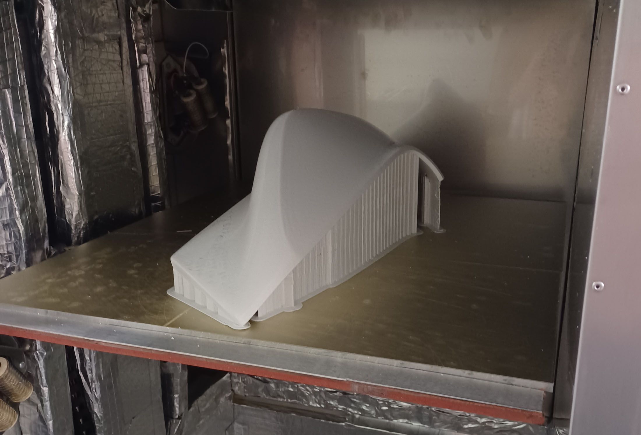
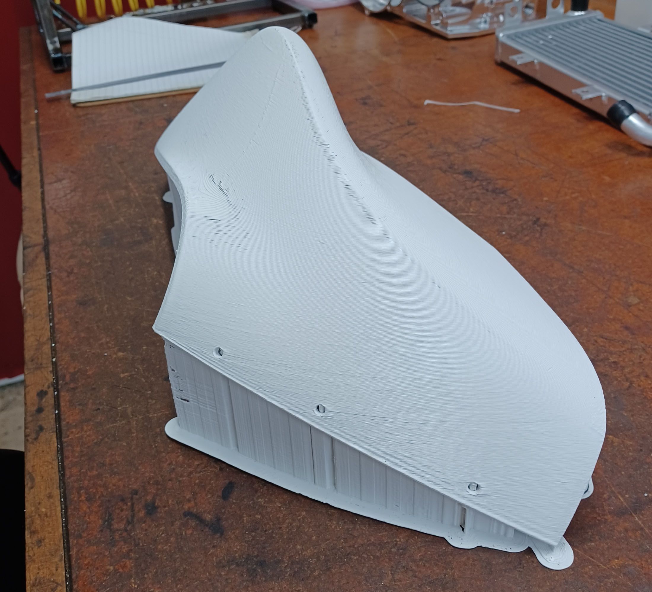
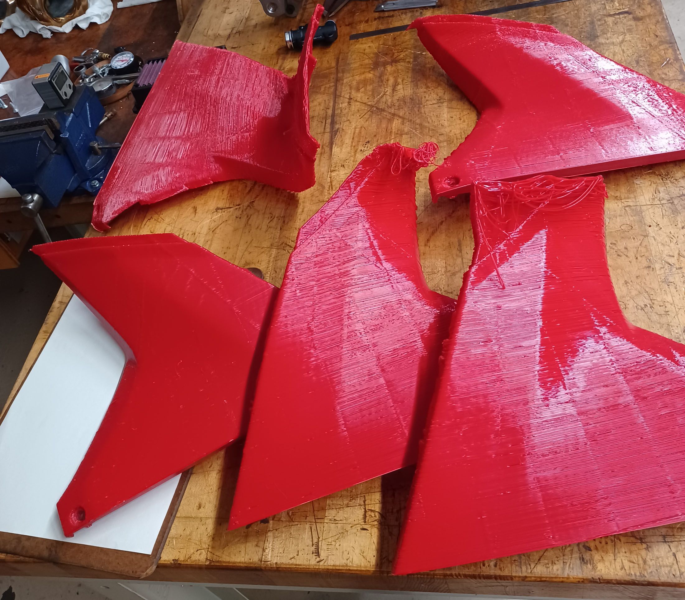
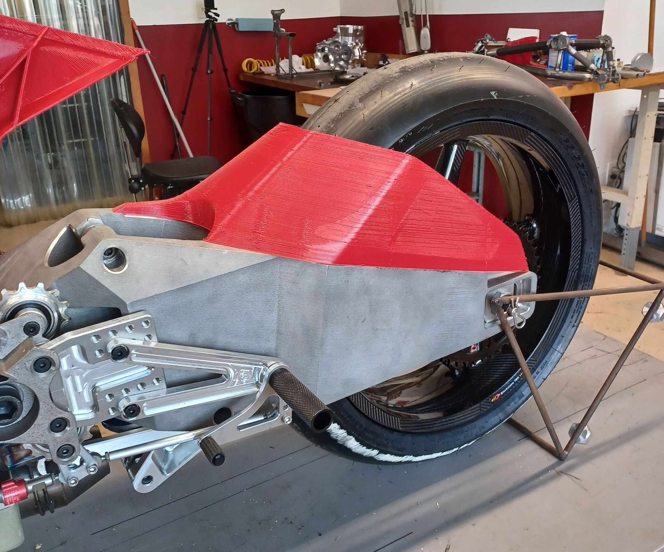
The step in the airbox part is because it was being run with no supports even with completely horizontal overhangs to see how bad the bridging was. A blob developed at one overhang and hit the nozzle and shifted the bed a little but it kept printing. I only wanted the first couple of inches anyway to check the assembly, since that is where everything mounts to.

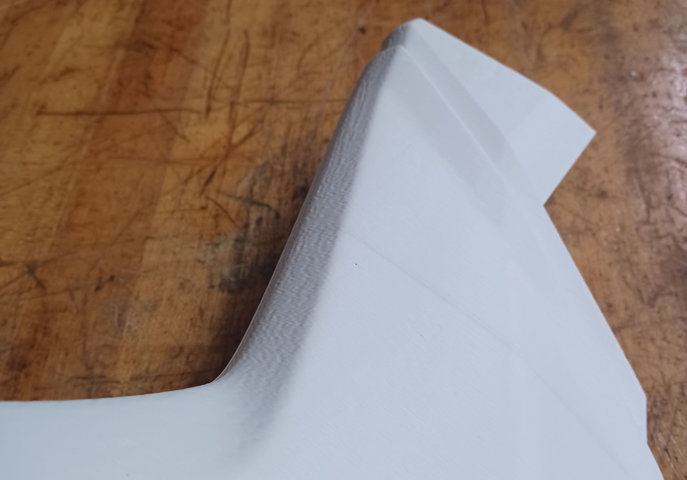
The marks on the back of the fairing parts are where I trimmed the ribs off but did not do a full finishing job. I'm very happy with the surface finish of the appearance surfaces. They have a consistent satiny appearance.
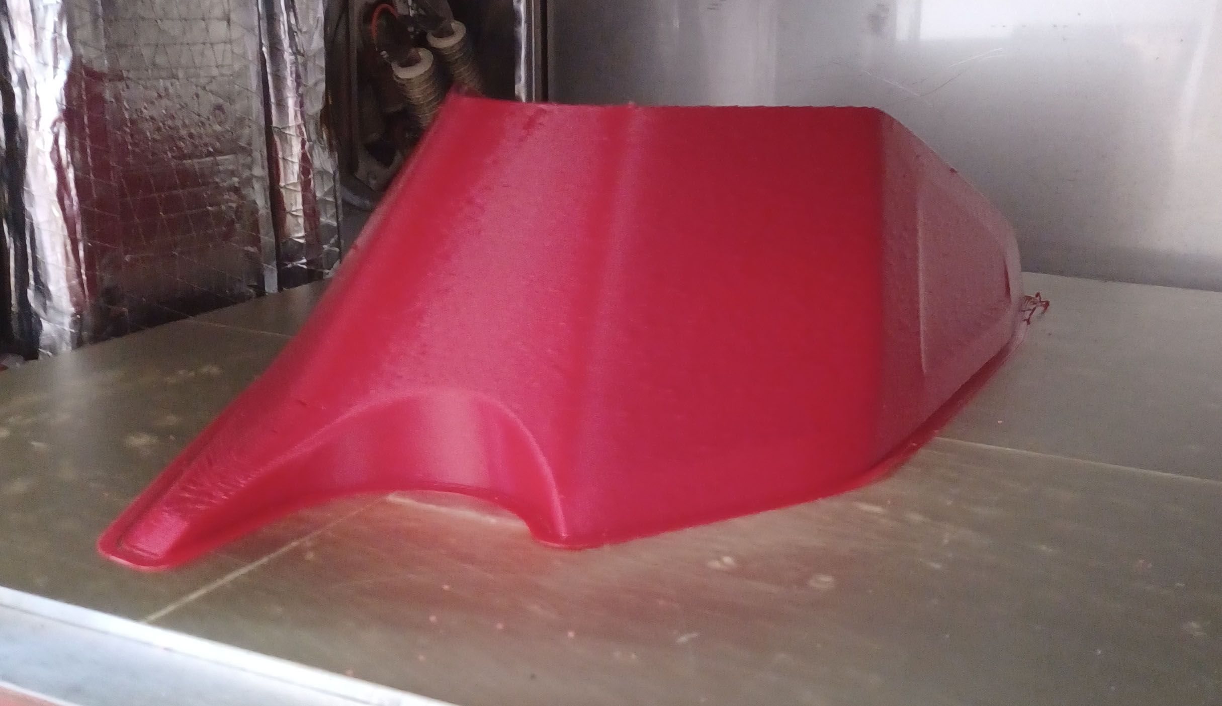
Now that I am feeling confident, one half of the gas tank/airbox cover is printing. Multiple smooth curvatures, some near vertical, some near horizontal. So far, so good. Projected to be a 13hr print and about halfway through. This is the first part with supports. I used the normal style as the tree support option resulted in a 2hr longer print time. Maybe I didn't tweak the settings optimally.
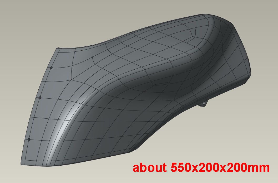
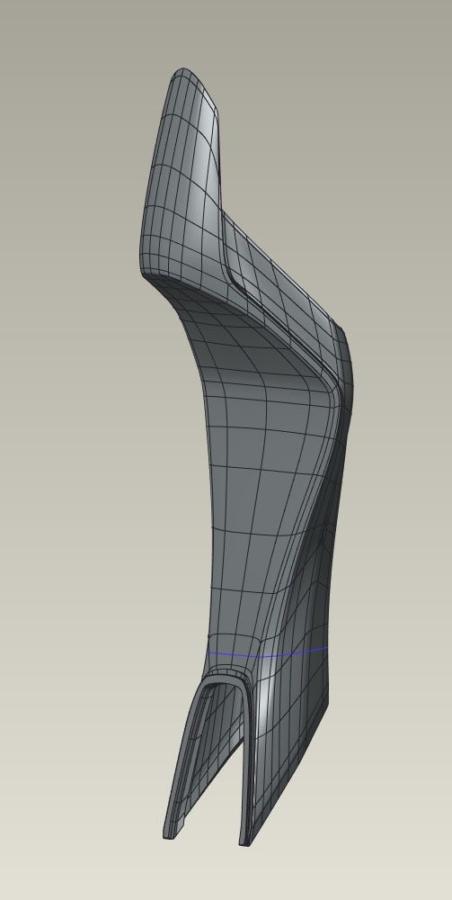
If that goes well, next I'll do the tailsection standing up, which is about 780mm tall, and really see how good the Z alignment, straightness, parallelism, etc are. I could print a large spiral vase box or cylinder and see quickly but that would be too easy!
Chris
Cosentino Engineering -
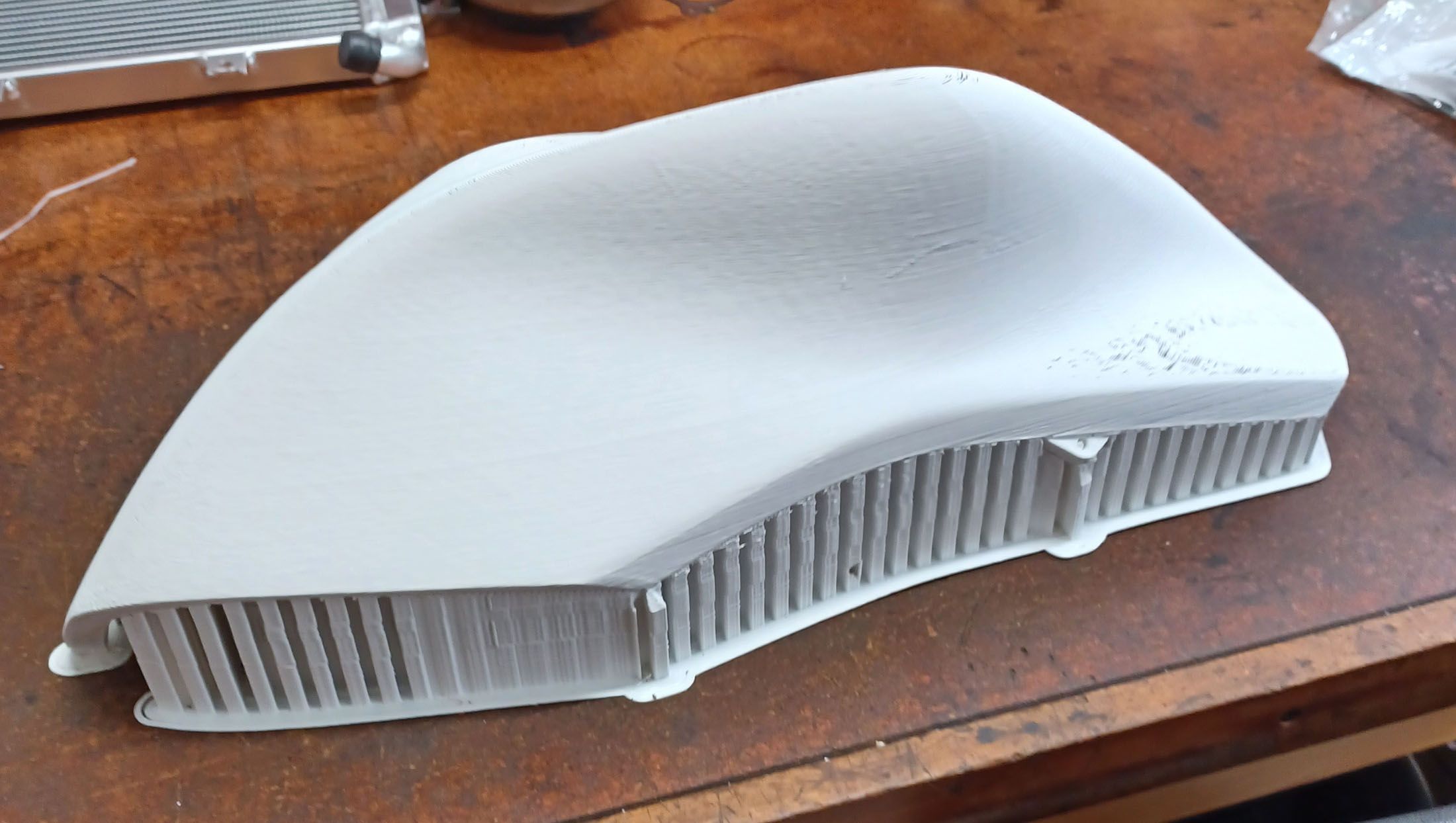
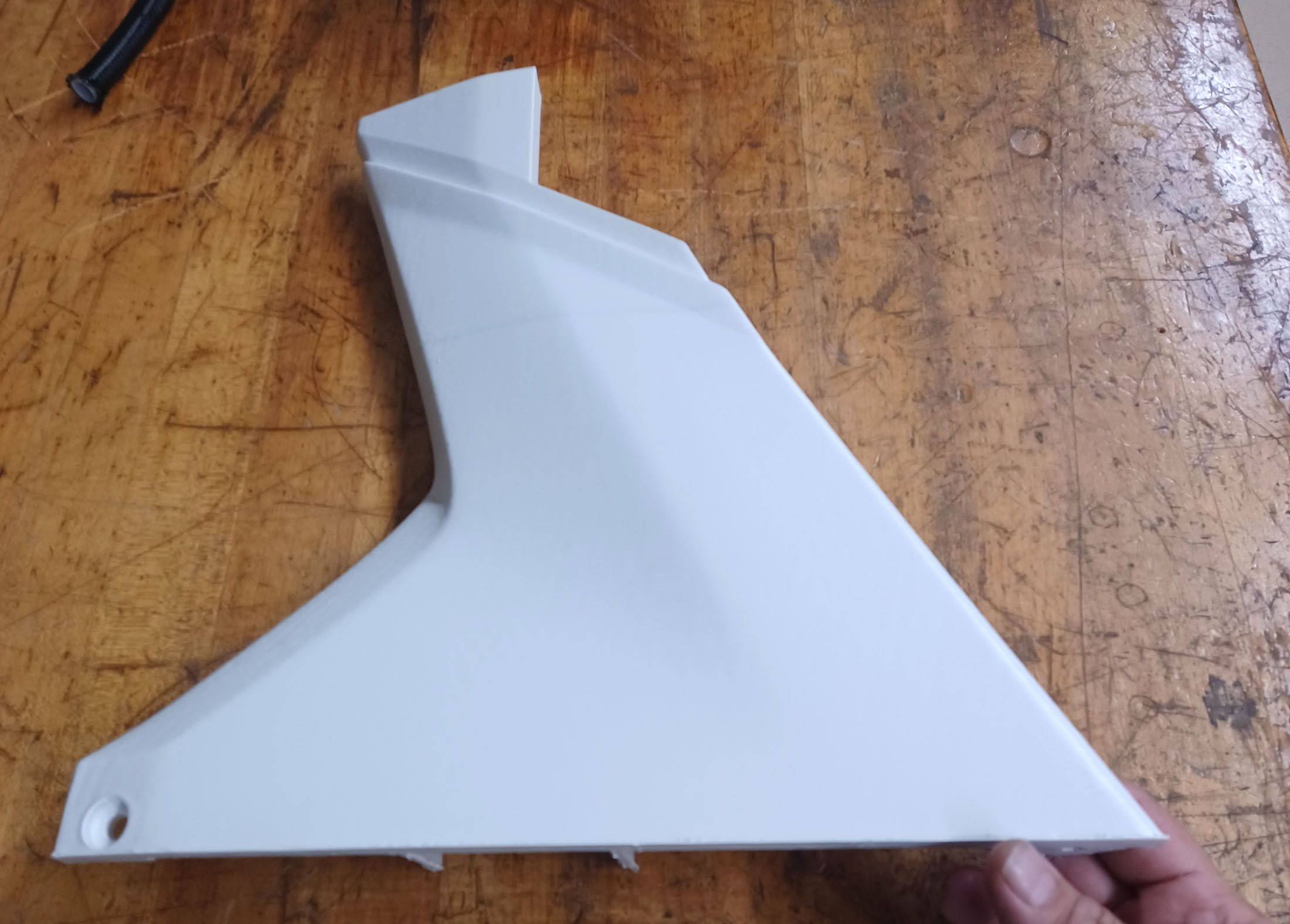
Oh yea! Finally after running this part about 20 times, here's a great final result. It is not the first white part, so was not a material swap fix.


It's just about as perfect a part as I can expect. The grooves on the backside are for 1/2" square steel tube for a small reinforcement frame that will be epoxied in and bolted inline with the two mounting holes so these parts will actually be used on the racetrack at up to 160mph.


The last few final changes were all thermal:
-added a layer fan, off for first 30% of build, then increasing to 75% at 75% of build.
-reduced the chamber temp as the build progressed, 50C to start, 45C midway, then 40C at 75%.
-increased minimum layer time from 10sec to 20 sec. Build time was 7hr2min.My take away from all this testing is that although it is often said to use minimal layer cooling on ABS, I suspect that this is for machines without a good thermal enclosure, which seems to make a big difference. I think that my air/temp mixing in the chamber is not that good, or the thermal gradient is just too big to keep constant with a thin bellows top with a gap for the printhead, or my sensor positions are reading low, or all of the above. With a 50C chamber setpoint, the bed sensor reads is 93 (set for 90) and the SSR never goes on. With a 45C chamber the bed is 92, with a 40C chamber, 91. So I am getting great heat retention to the point of excess, where the chamber heaters are heating the bed. Which really just means I have to figure out those numbers for this printer. Or maybe the heater tuning should be with all configurations of the various heaters on and off, but then it gets pretty complex and more likely to mess things up.
Once things get up to temp they are quite stable so I don't want to mess with it too much. So I’m getting there. Hopefully a revised layer fan will reduce the amount of heat soak, for lack a better term, and allow me to do 10sec layers instead of 20sec. Or I’ll just print two parts at a time. But for now, it is 235/90/50 to start, then dropping to 230/90/45 at the midpoint, then 220/90/40 for the end. Max speed on the big layers is 150mm/s, down to about 40mm/sec on the small layers.
Thanks again to all for the help!
-
 1
1
-
-
I love the embedded nut idea! The multiple pauses is dedication! Great idea and flag choices, 😉
I'm going to test the parts on track as-is. There is a lot to be tested for rider ergonomics and maybe even some wind tunnel time. Once I am happy with the entire design, I'll have an autobody shop (lots of cars use ABS bumpers, etc) sand and prime to get a great surface finish then give them to the CF guy who will make molds from them and make final CF parts. Acetone smoothing works on small stuff but think these large, gently curved surfaces will end up looking like warped glass and I don't think will make the final finishing any easier.
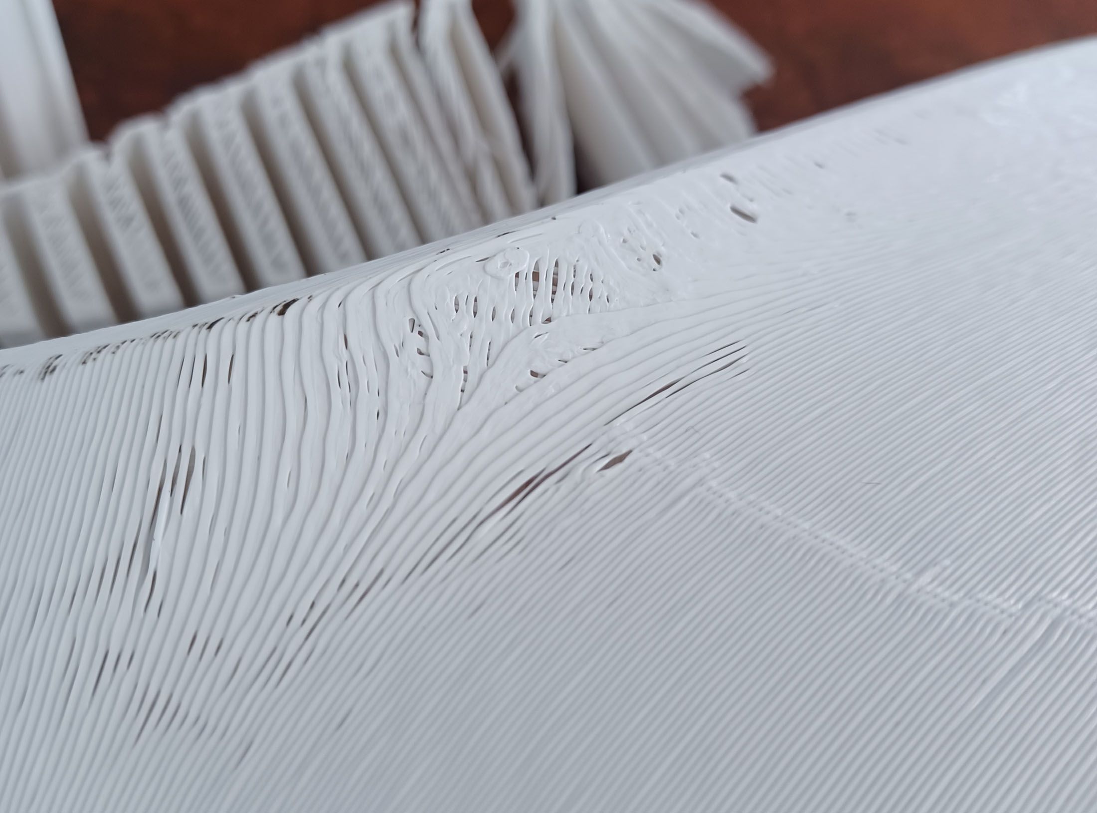
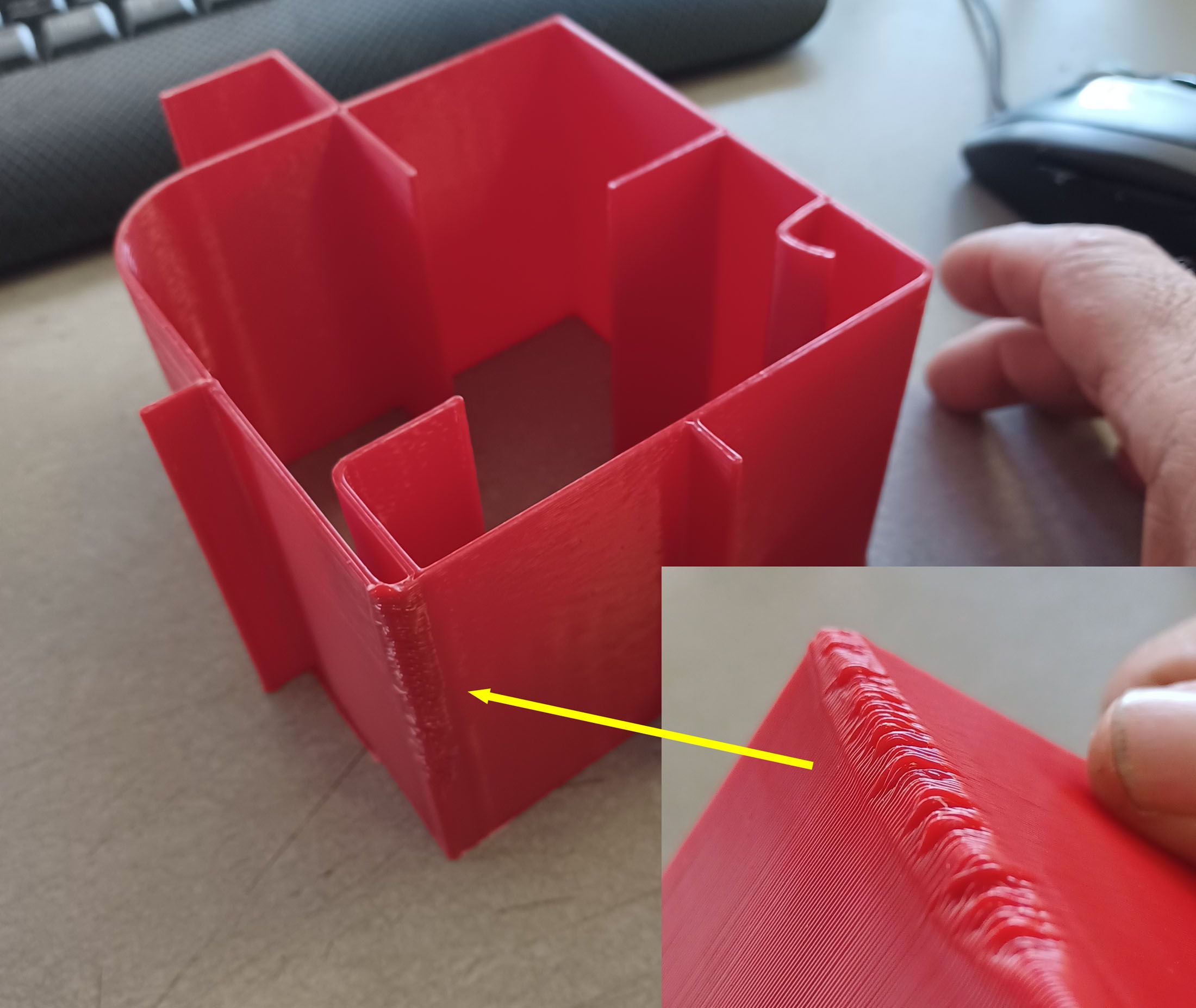
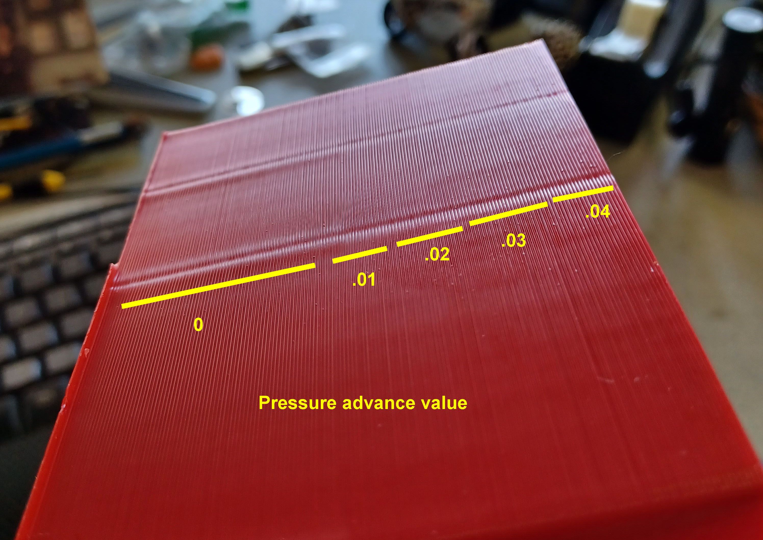
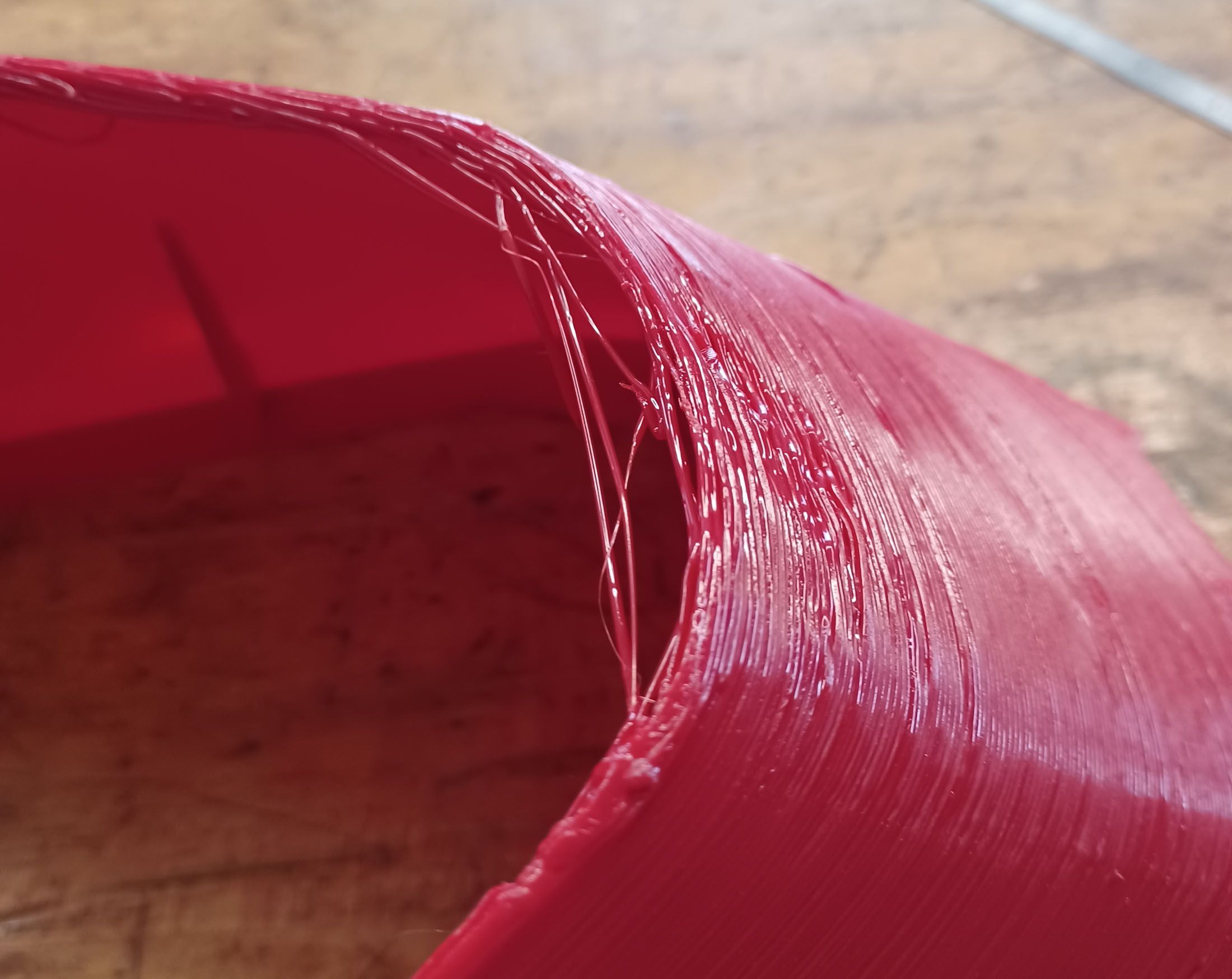
Made and ran a PA test part with geometry similar to my problem areas. This part's toolpaths are one continuous pass per layer, no infill, retractions, etc. 0.8mm nozzle, 0.5mm layer height. 135mm/sec actual print speed.

It printed mostly great, with the exception of one area:

The location of this problem points strongly to thermal issues of the extrusion bead cooling, so next on deck is the layer fan.
The PA test changes were subtle and easier felt with your fingertips and not a camera. Best value seems to be 0.03 where there was the least amount of bulging at the rib ends but no other weirdness at corners and transitions.

Progress!
-
1
-
-
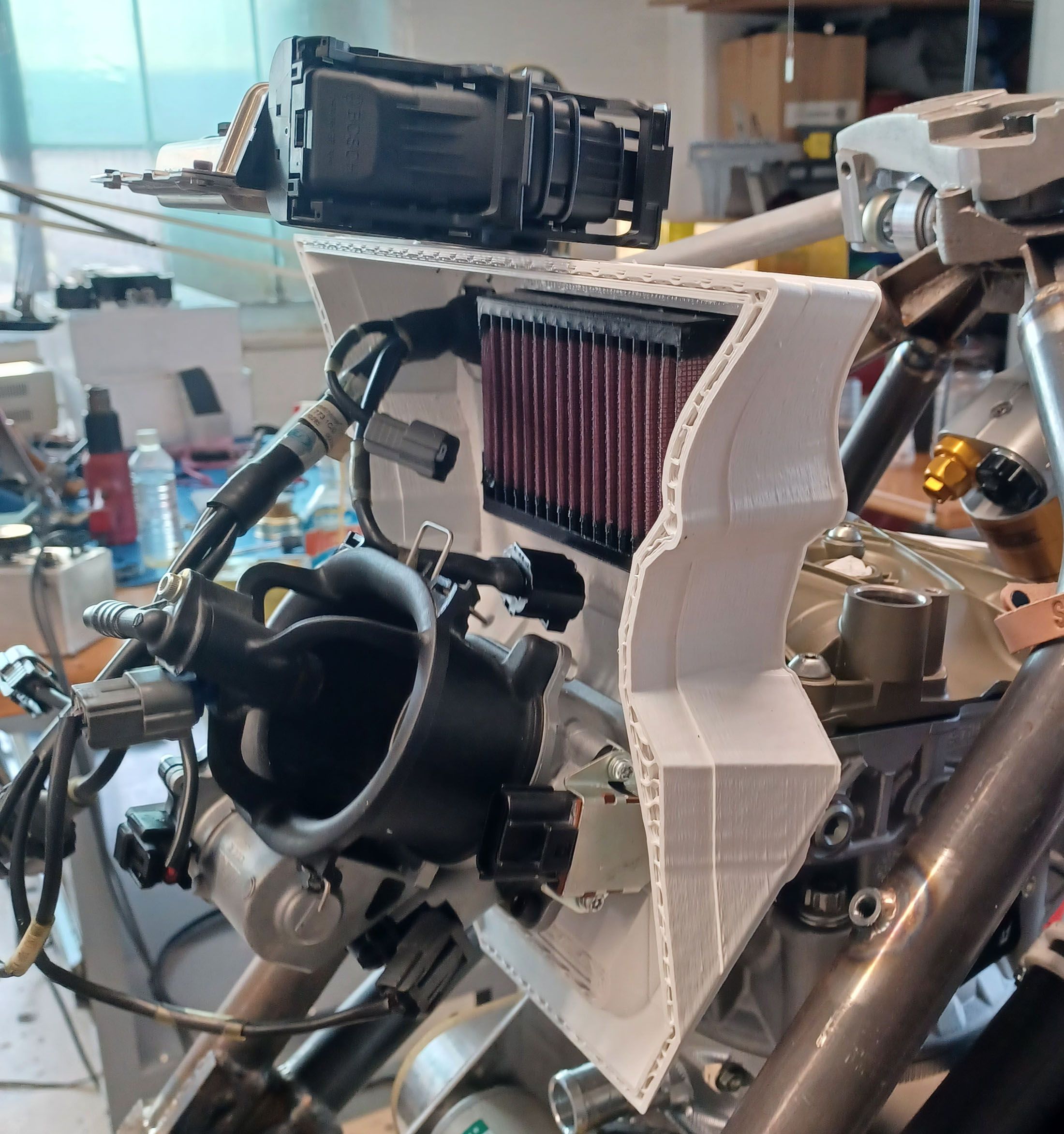
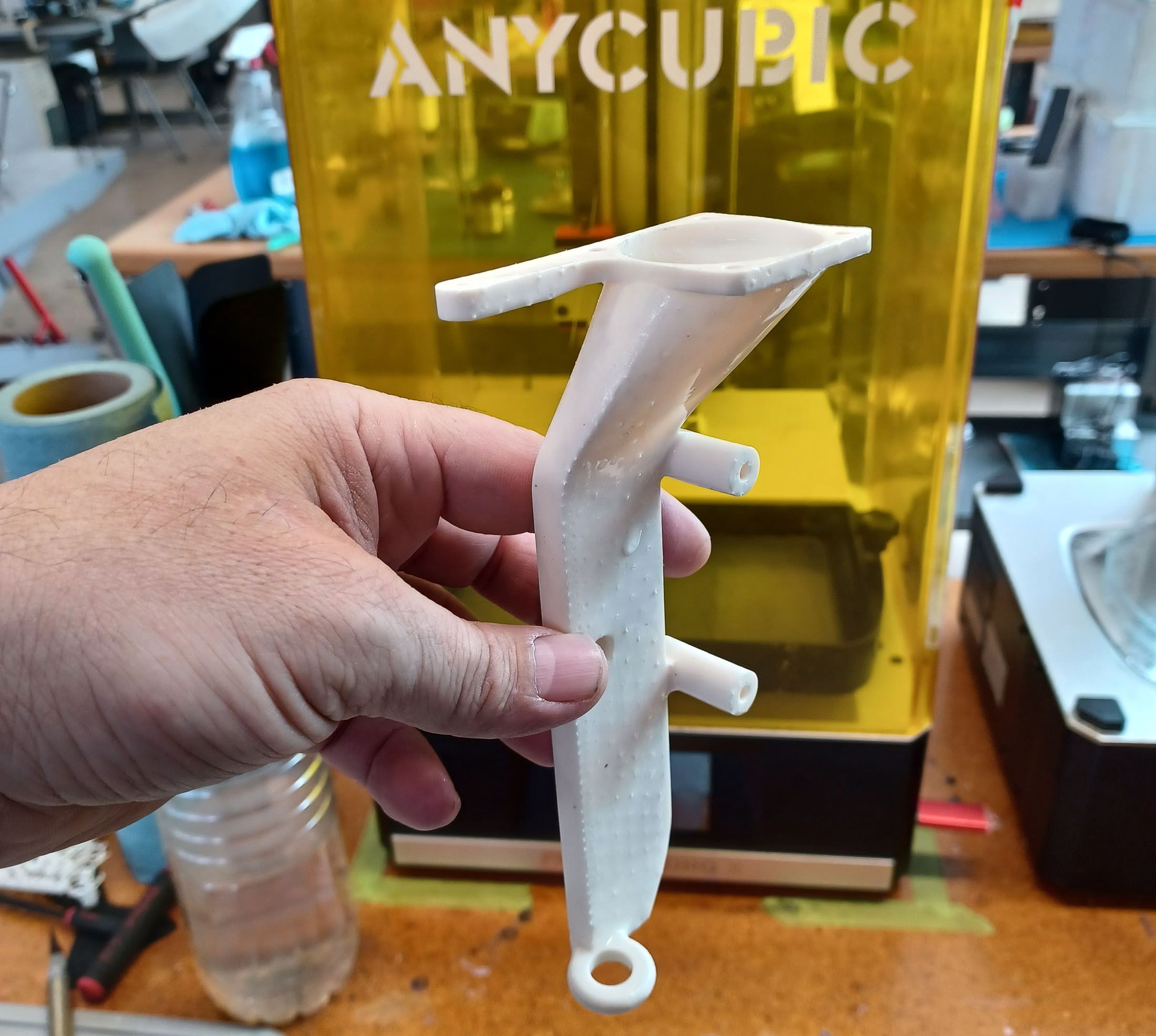
Well, the fan mount needs a rev2 since I did not have all the bellows mounts in the CAD model and reality overrides CAD. 😞
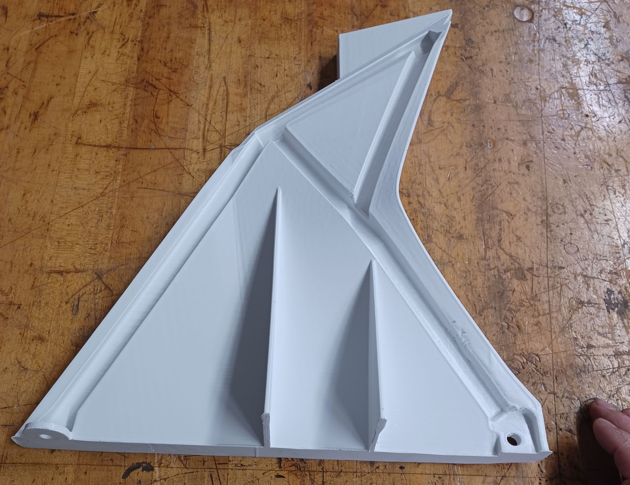
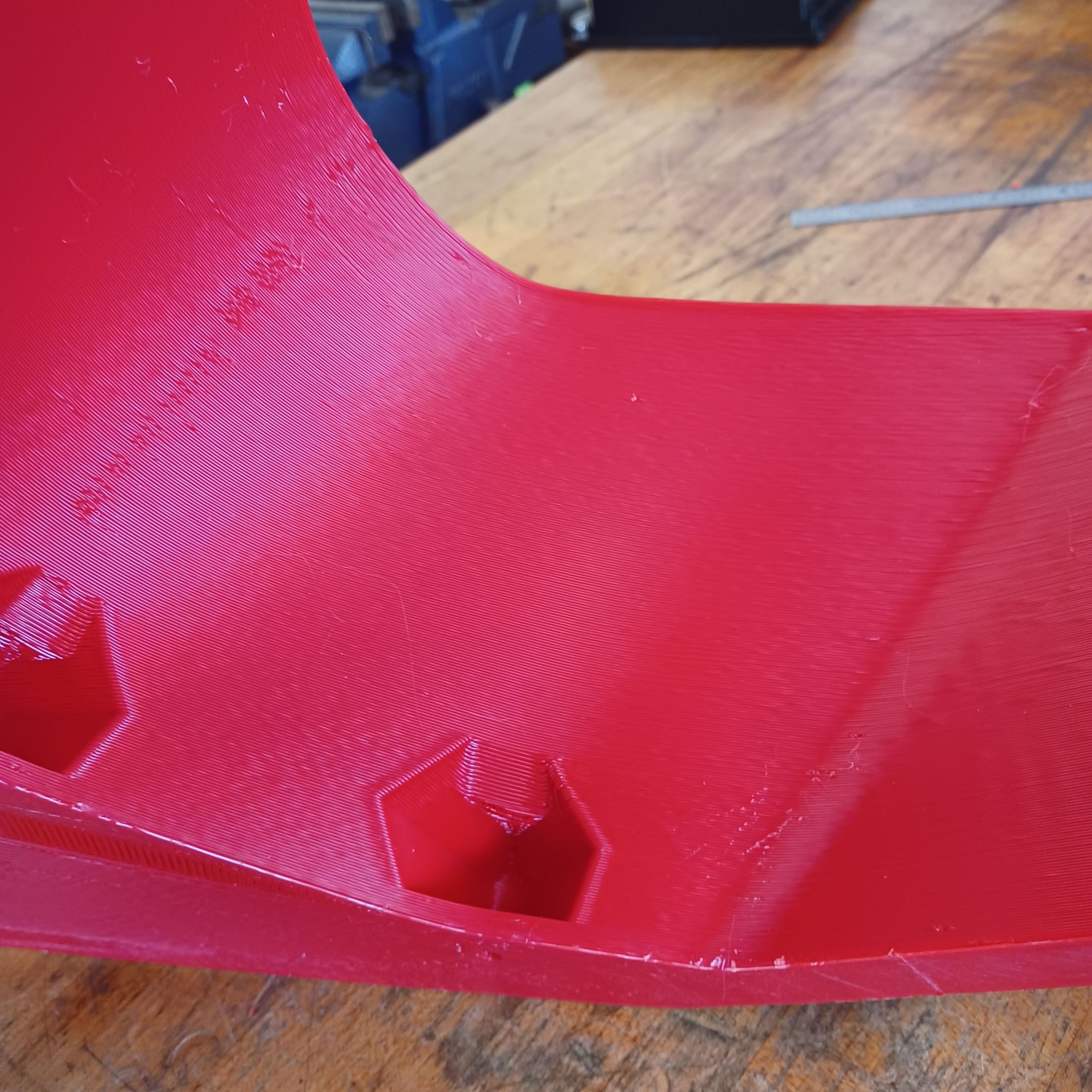
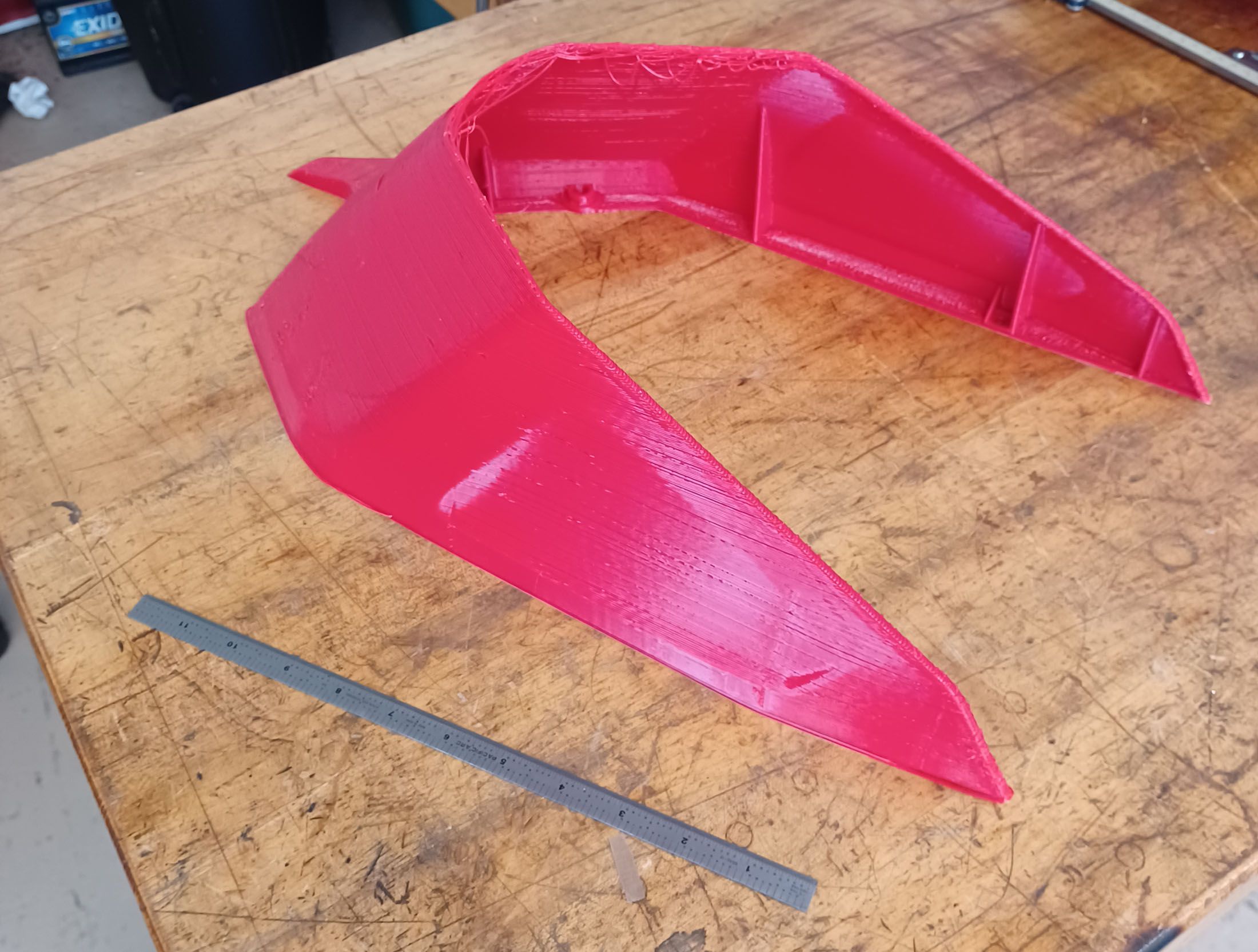
So overnight I modified the swingarm hugger part, which printed pretty decently as a thin wall part, to be a solid like the previous subframe side panel. 5hr35min, and I think came out quite good. It is definitely better than the thin wall version, not much heavier, and a lot stiffer. This does point to me pushing the geometry limits a bit with the complete thin wall parts, but I will still try to find settings to eliminate those rib end issues and install the layer fan. The problem is this thickening technique is not applicable to all of the parts. I will do it when possible, but will dedicate today to running some calibration processes (pressure advance tuning, etc) in the hope of getting both types of parts running well.


Instead of the ribs of the previous runs, this is modeled as solid with some cutouts for the mounting holes.


There are a few printing artifacts and hopefully today's activities will help to address them, but I'm very happy with these very usable parts.
-
I'm reluctant to start trimming prints since then the tests are not really representative of the thermal operating conditions. I'm in this project about $6k so far and have wasted more filament with spool slack system problems than with bad prints!
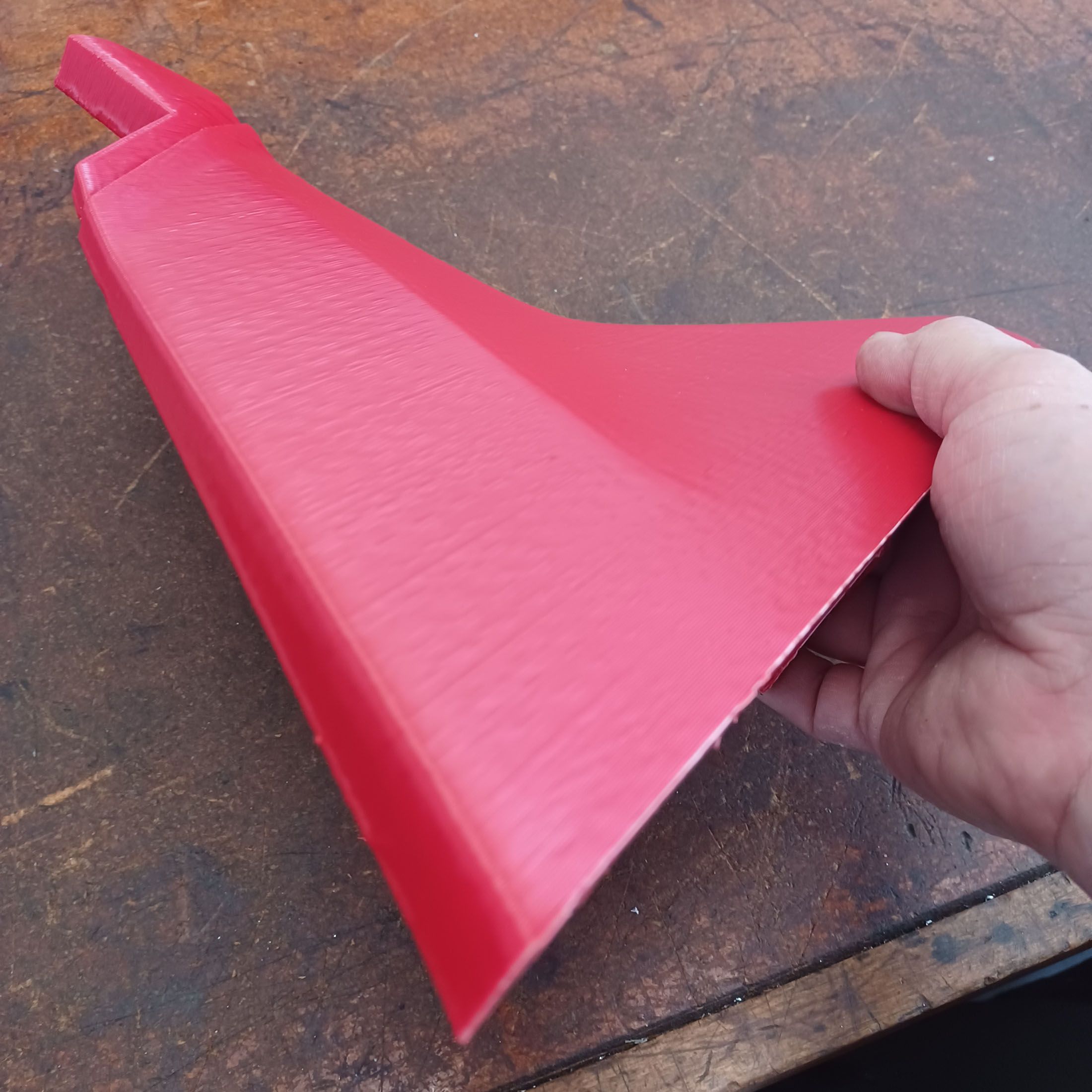
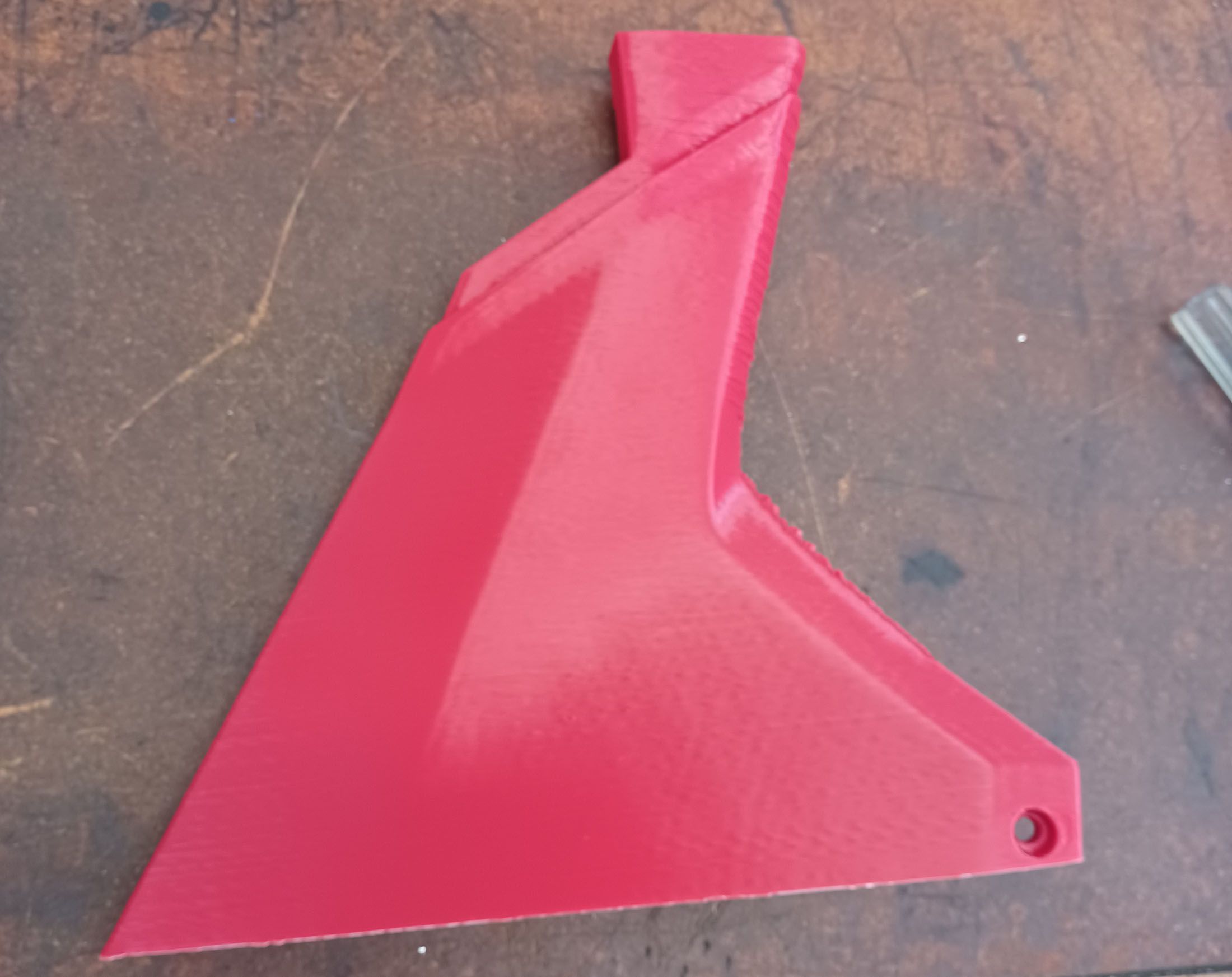
Last night I made some modifications to the part to see how much of the thin wall nature is the issue. I thickened the part to about 20mm and sliced it with a 0.8mm nozzle, 0.4mm layer, 20% gyroid infill and 2 walls. The result was the best yet, with a 5hr3min print time.

I'm really happy with the surface finish and if this last issue can be resolved will consider the printer a complete success.

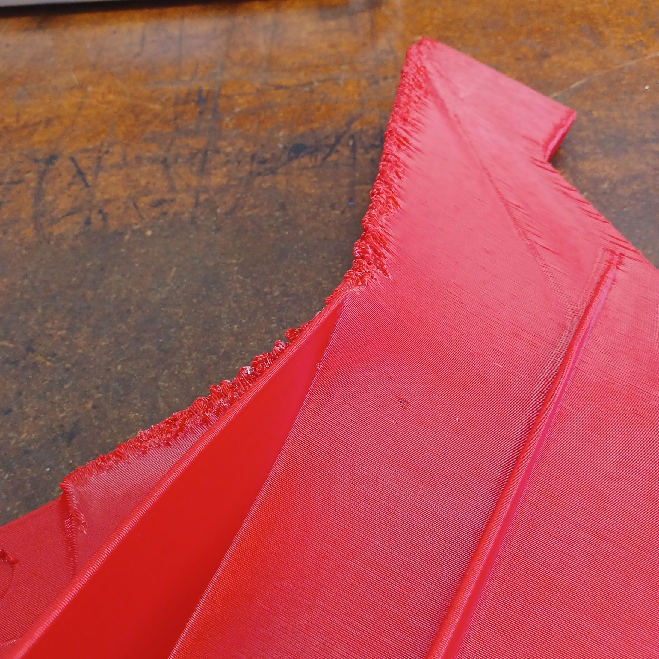
Though the same problem happened along one of the inner edges.

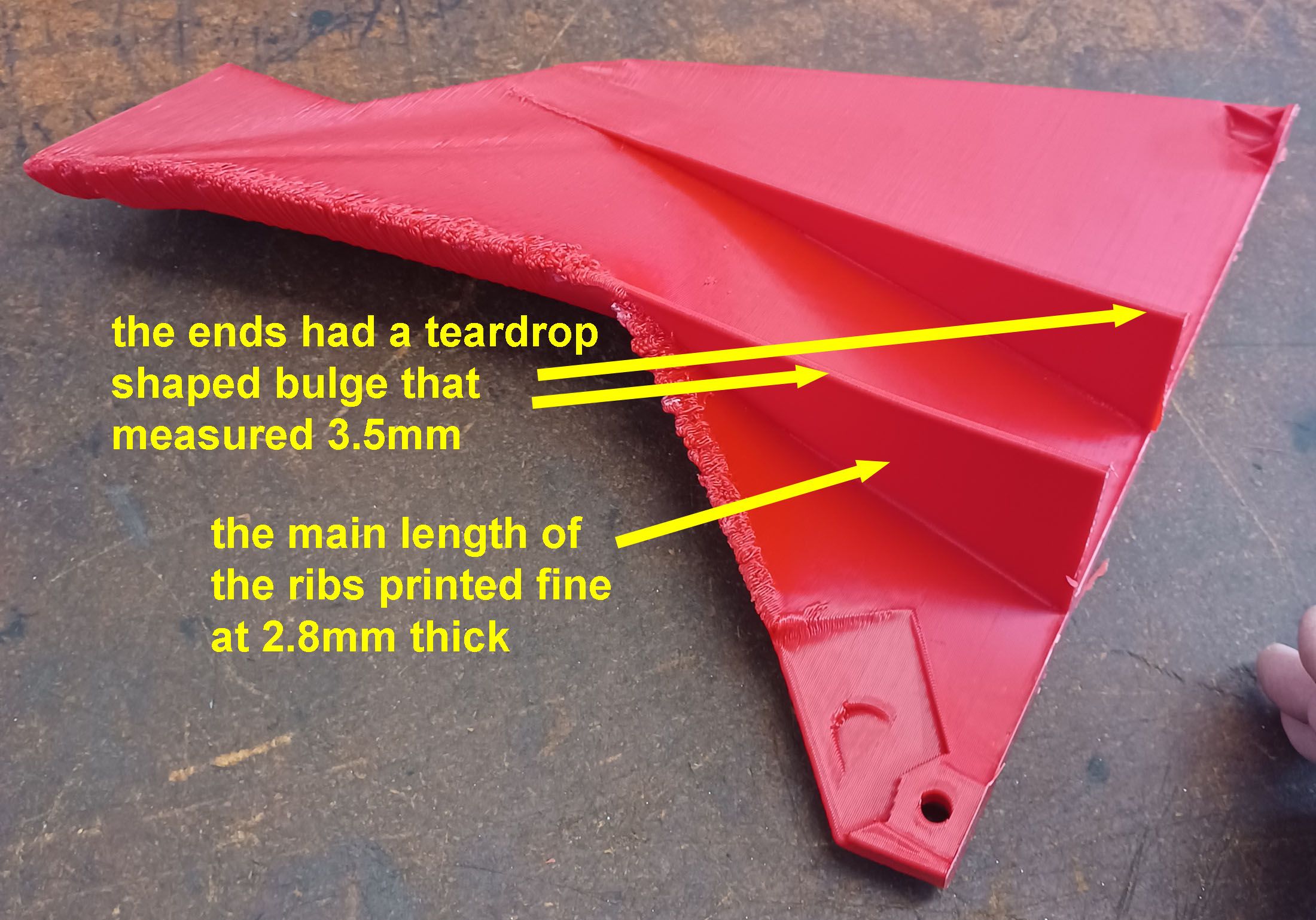
The narrow ribs with no triangular ends (done to try to make the problem happen) printed great, through they did show signs that pressure advance could be beneficial. Most of the wall was 2.8mm thick, but it fattened up to a teardrop shaped 3.5mm bulge at the end. But unfortunately my attempt to induce the problem was not successful.

Now to install the layer fan and duct and run the same file again, modified to turn the fan on after 100 layers.

Chris
-
1
-
-
This same problem happens on a bunch of areas from about 1/3 up to all the way up, including where the layer time is about 40 sec. If cooling is really an issue I think a layer fan is a more direct solution than slow printing. Though if all else fails I'll try that too! I have a layer fan shroud printing now on my resin printer in Siraya's high temp material, which held its shape in a toaster oven that was set to glowing.
Another possible answer that may not be too unrealistic is that I am really pushing the limits for a no support fdm print with thin walls. For this part I was able to convert it to an about 20mm thick solid and while the resin printer is going with the fan shroud, I will try to print this thickened part with a normal infill technique and see what happens.
-
>>In this image it looks pretty darn good below my yellow line
Yes, if the entire part was like that I'd be quite happy and impressed with myself. 😉
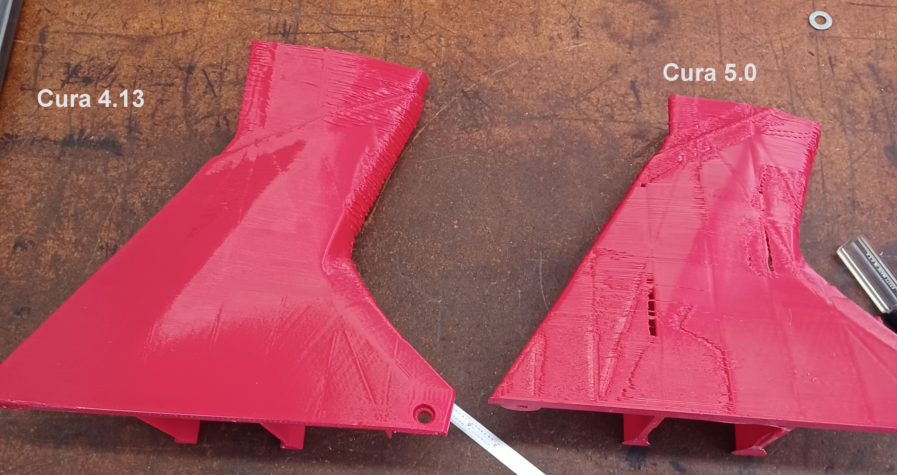
>> I don't know the toolpath and just thinking out loud
Please continue! I'm at a loss so would think about any new avenues to investigate. The toolpath is clean, two inner passes, then one outer wall, all with no retractions. Cura 4.13 was key in simplifying the toolpaths from 5.0's variable width complexity. It is a weird problem and as much as I search, nobody else seems to have had a similar problem.
>>have you played with the extruder Acceleration setting
I have the retract at 1.5mm and 25mm/sec but do not see any extruder acceleration settings. But the paths don't have any retracts at those areas.
>>I know you've adjusted the pressure advance
I am going to install a layer fan and turn the pressure advance off for now, as the PA did not seem to have any affect on the problem at hand. Slowing it down is against my personal nature, and a lot of the same areas print fine, so just need to find the key.
-
Tanks for all the help.
Yes, I am keeping track of all the variables. The easiest way to run in circles is to not look where you've already gone.
The bed slinger style printer introduces a lot more dynamic inertia issues with faster printing that a CoreXY does. The filament extrusion inertia idea is a little of me grasping at straws: possible, but unlikely.
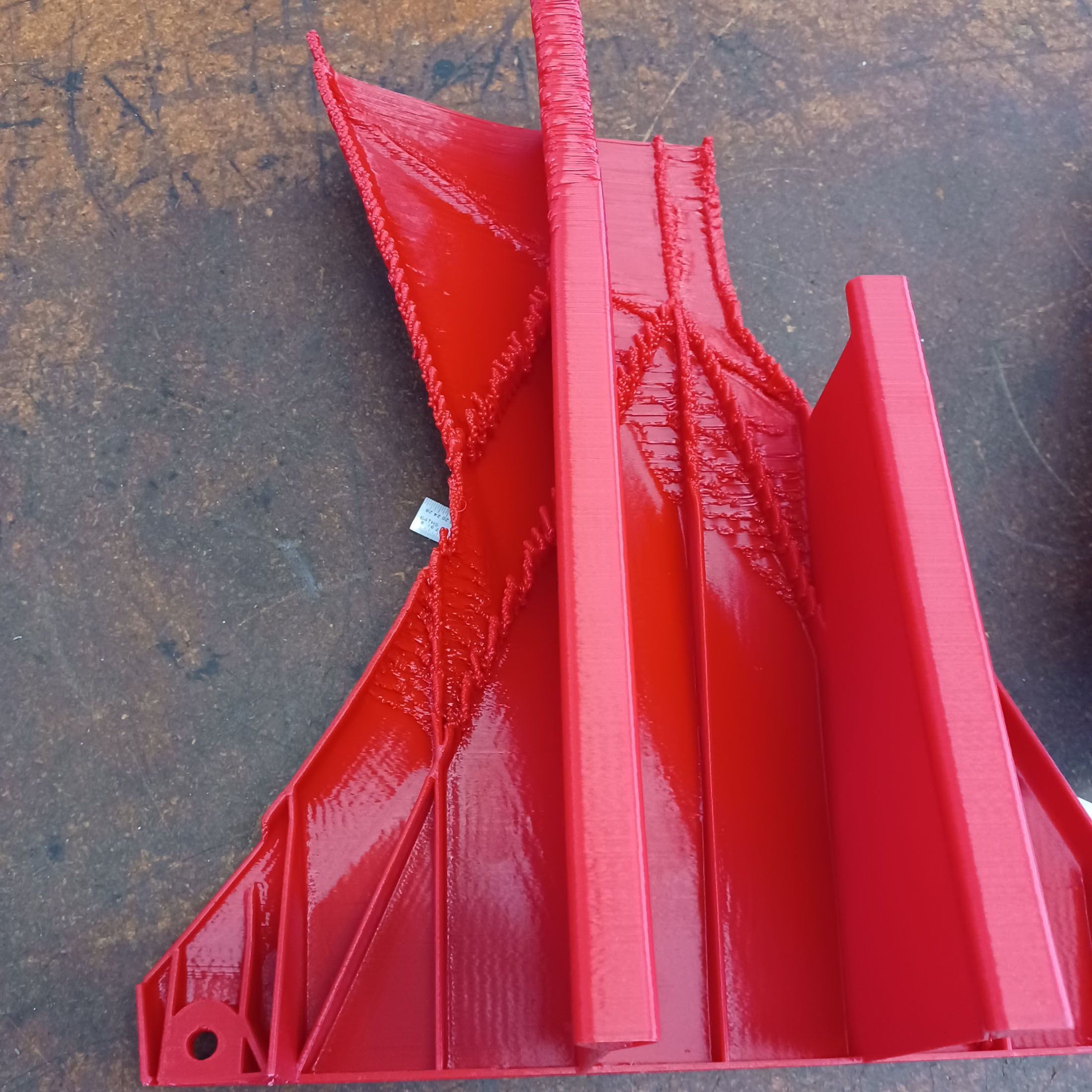
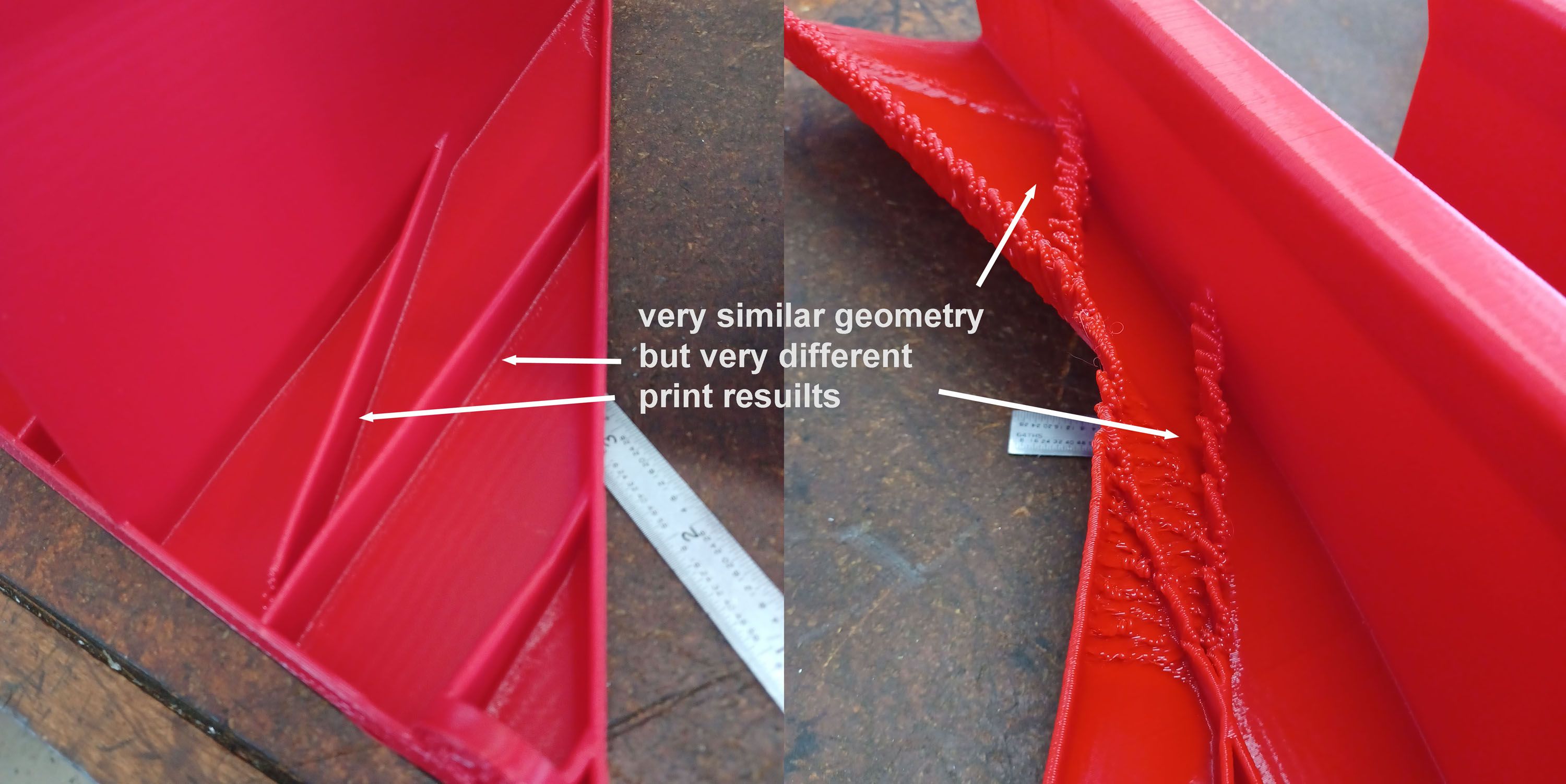
Even though my next step is a layer fan, I am a little skeptical that heat is the issue. On this section of the print, which is about 75% done, there are perfectly formed rib features right next to ribs with the weird misprinting.

Would these areas that are so close together be printed so differently if it was a thermal issue?
During printing I am able to tap on the top layer before the next layer is printed and the plastic feels hard, not soft and mushy, but that is a few sec after it is printed, maybe it already has malformed, dooming the next layers to follow suit. I may be resigned to having to sit and watch it until I can see it actually start to happen and hope to glean some insights, but it is a little tough since all I can see through is the slot between the two bellows.
-
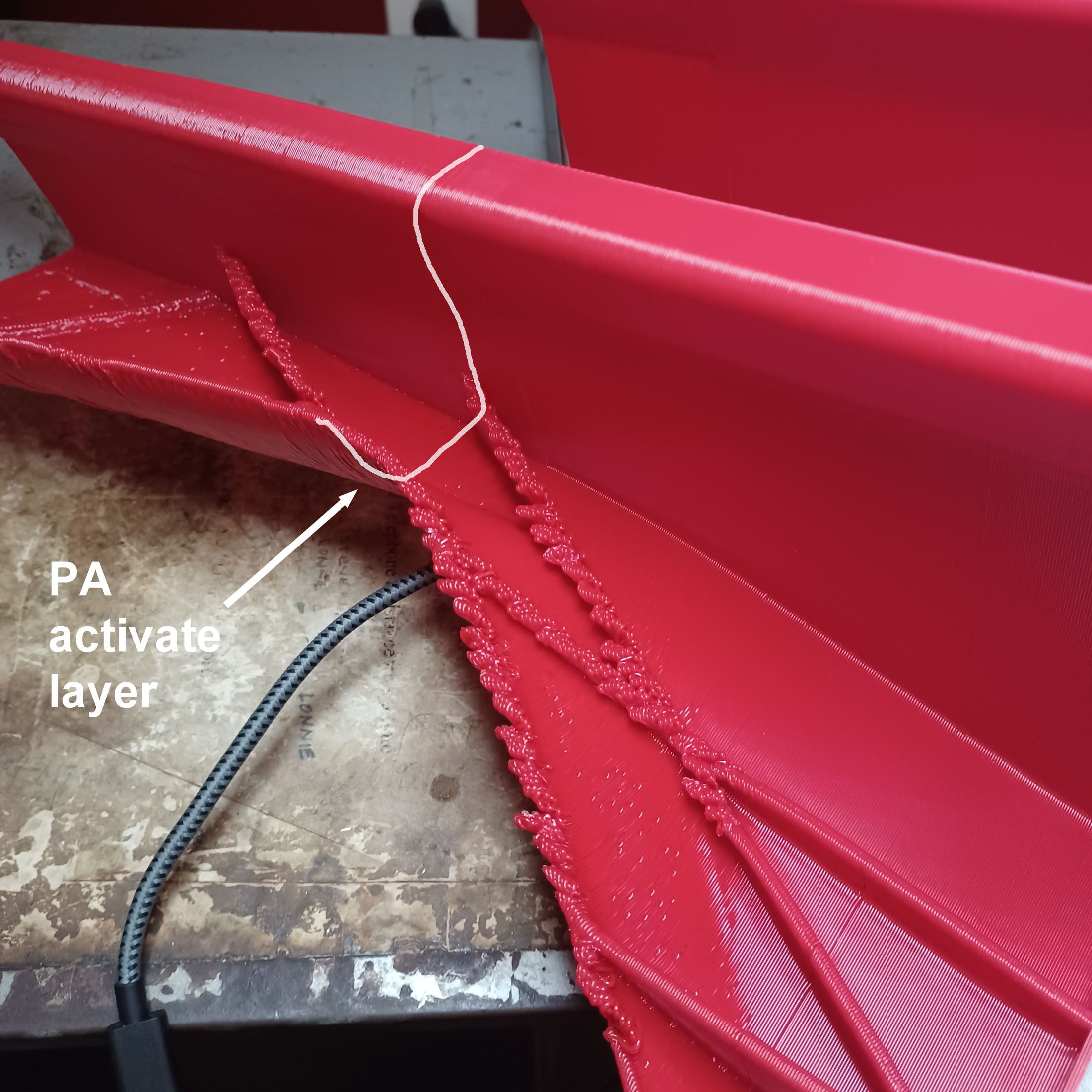
OK, making some progress. This is the first 0.8mm nozzle part off the machine. 4hr3min print time, 0.4mm layer height. About halfway though the print I activated pressure advance with a 'M572 D0 S0.10' command.

The change did not eliminate the rib end wiggles, and in fact one wiggle that was already happening continued to happen.

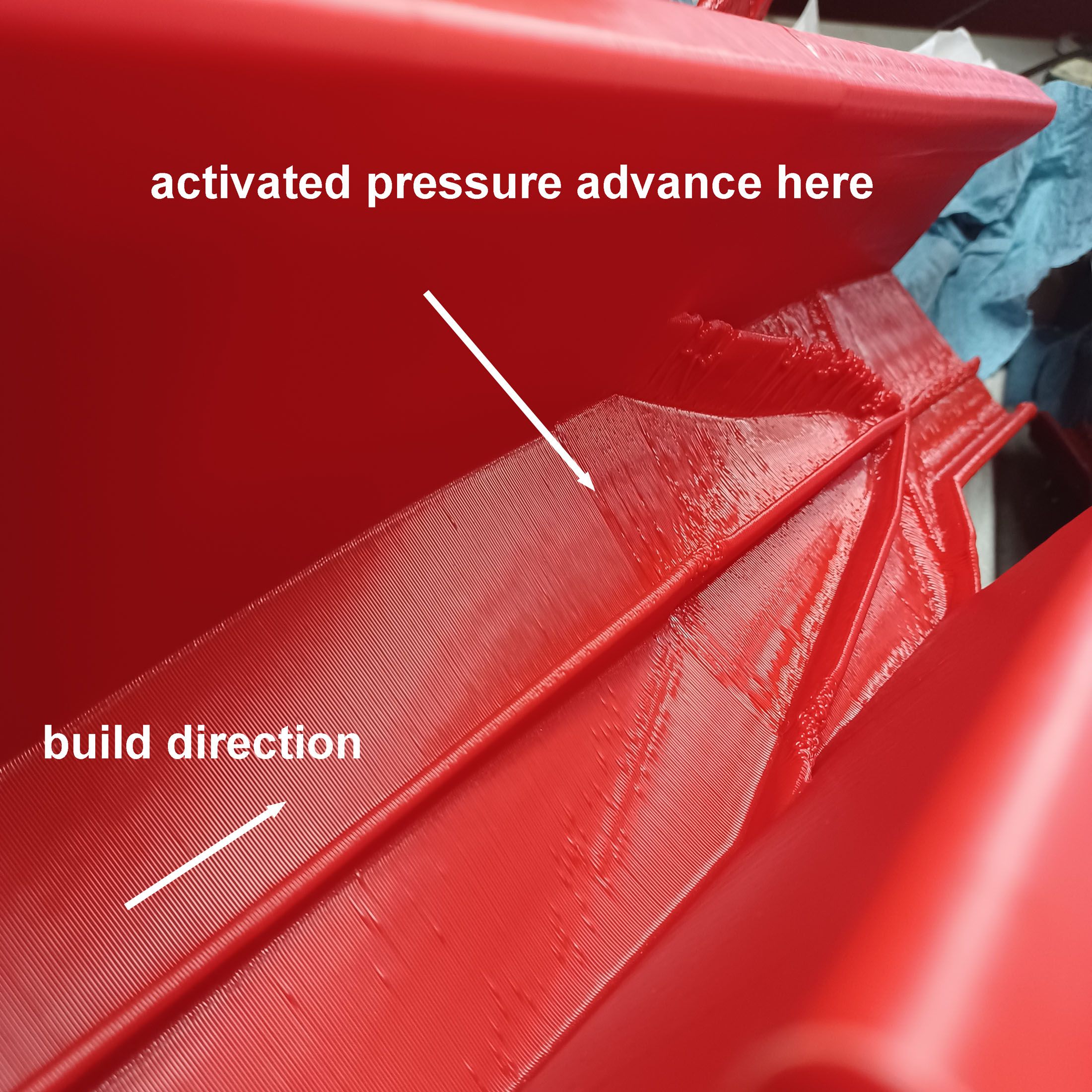
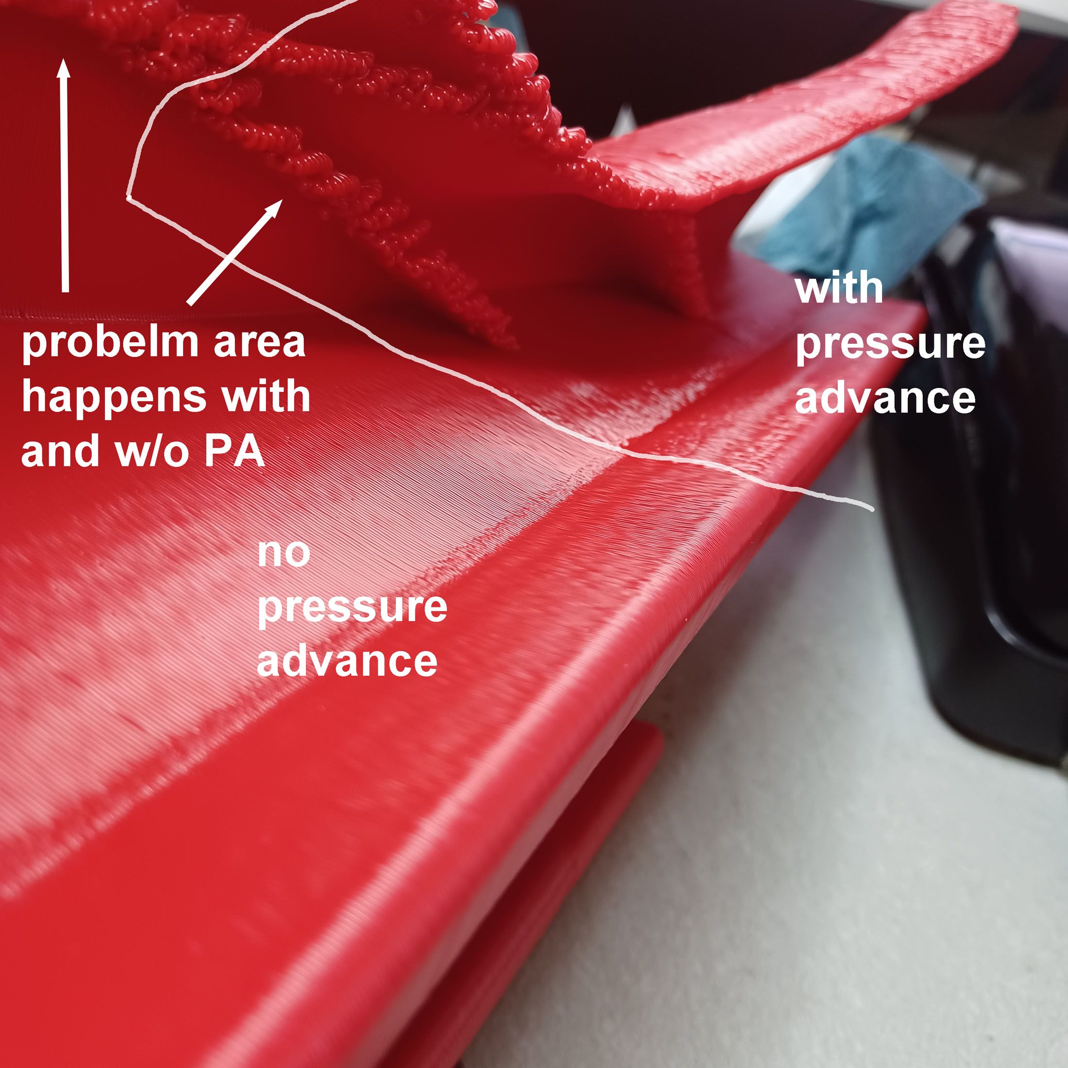
There was a visible difference in the accuracy of the toolpaths, with the no-PA areas showing a better finish and more accurate toolpath than the areas with PA.


The two tall ribs with the triangular ends was where the accuracy difference was most apparent. It seems that the PA was causing a decent variation in the extruded line width. The no-PA areas were triangular and straight while the lines in the areas with PA were not straight and had some convexity to them. Looking at the top layer it seems that the lines were thinning at each end. Maybe the S0.1 was too much PA?I'm starting to wonder if the inertia of the extruded bead is causing it to flop over when the printhead changes directions quickly. Or something dynamical like that, since the gcode is clean and there do not seem to be obvious mechanical problems.
I think the next test is to add a layer fan to see if cooling them quicker will prevent the problems. Though I do have second thoughts about that approach, since looking at the close-ups in the previous post it seems that there is just too much material being printed for the layers to stack on each other cleanly. They seem to be all jumbled together with no room for proper placement. But on the areas without such an abrupt direction reversal the layers are stacking very cleanly, so is it only on those areas with an abrupt change in direction. Weird.
-
6 hours ago, GregValiant said:
The "SmartAvionics" guy is @burtoogle here. You can maybe reach him through his https://github.com/smartavionics site. He maintains his "Master" branch of Cura there.
OK, thanks. I just printed pa part sliced wtih 4.13 and it came out a lot better, but still those weird problems on the end of the ribs:

Except for those weird problems at the ends of the ribs.

Some places it prints perfectly, some places, not.

This is frustrating, sections of the print are perfect so that means that a lot of things need to be working correctly, and sections are crappy so means that something is amiss. I have a 0.8mm nozzle sliced part printing now with 4 printhead passes per layer. So far, so good, but it is only 75mm into the print.
As an aside, I am realizing the speed limitations are mostly the extruder, not the XY motors. With the smaller nozzle and layer thickness the print speed is a lot faster, so even with 2x the layers, it is only a 4 hr part as opposed to the 3 hr with the 1mm nozzle. Printing is now at 100mm/sec actual and rapids at 750mm/sec. Maybe once it is printing consistently I'll get a bigger motor for the extruder and see how fast it can push filament through.
For extruder calibration, is the 'mark and measure' or the 'extrude and weigh' a more accurate approach? Or another technique?
-
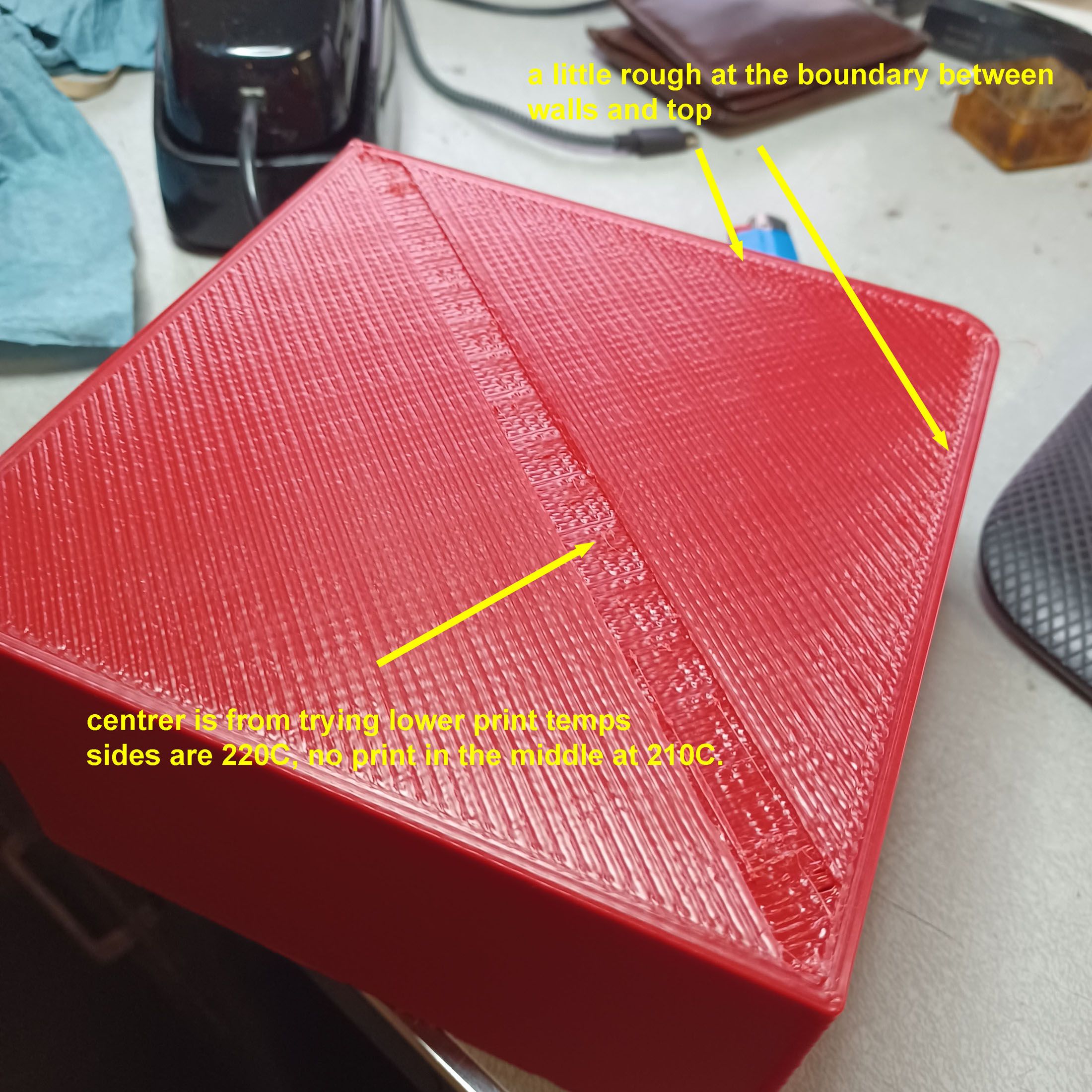
OK, just printed a 150x150x75mm block with 20% infill and it came out quite nice. If I can get the fairings to look anywhere near this good it will be a success.

The top surface fill was a little rough where it met the walls but otherwise was good. The middle section was me trying lower print temps, the good parts were 230 to 220, the non print is 210, then back up to 220.

Got 4.13 reinstaled and the gcode preview in 4.13 had much cleaner toolpaths with none of the weird artifacts from 5.0. So I am printing a part one out now with a 4.13 sliced file and tomorrow will fit a layer cooling fan to help the small top layers solidify properly and hope that seals the deal.
-
>>How are you powering the bed and hot end
The system is run by a Duet3D 6HC. The bed is powered by 220VAC wall power and controlled by a SSR. The hot end is powered by a 24VDC line running through Duet3D's tool distribution board to a 1LC toolboard that is controlled by a CAN line. The chamber heater is powered by 220VAC wall power and controlled by a second SSR.
>>I think I'm seeing a persistent problem with extrusion. Even the Benchies have what appears to be some over-extrusion on the decks (I think skins give a better indication of over-under extrusion than walls).
Yes, I have noticed that the flat 3dbenchy surfaces and the top of the bodywork flange have a consistently rough finish. The hull sides do look quite nice though, and that is the type of geometry that the vast majority of my parts are. I didn't want to change the extrusion setting and potentially mess up the relevant areas that came out nicely in exchange for improving the area that I don't care about. Printing kills so much time it is hard to test everything. And maybe rushing is part of my problem!
>>Have you tried slicing in 4.13.1? Yes, there are new settings in 5.0 but I'm not 100% sure they are dialed in within Cura.
I have not. I use a resin printer a bunch but am much less current with the state of FDM slicing and the best software/releases for it. Am trying to get a response from the https://smartavionics.co.uk/ guy who did a custom Cura build for thin wall parts to see if he has any suggestions.
Going back to a pre-variable line width Cura may be a good suggestion as I do not want varying extrusion size, just the same exact size layer after layer.
Thanks for the help.
-
Had a frustrating few days, starting with the bed heater temp sensor going bad. At first I was not sure as no errors were thrown, but then I was getting heater faults and saw obvious spikes on the graph. To get printing again I mounted a PT1000 sensor embedded into the aluminum bed and now it seems it be working. Reran the M303 cycle on the bed with no warnings or errors. Also had a couple of mechanical gremlins that had to be fixed. Also did some print temp tests and reduced the nozzle temp from 250 to 235C.
So, after this tweaking I was able to finally get another part to finish printing. Results are somewhat mixed, but at least it finished! I am a little frustrated as the results are still worse than the first part off the machine!

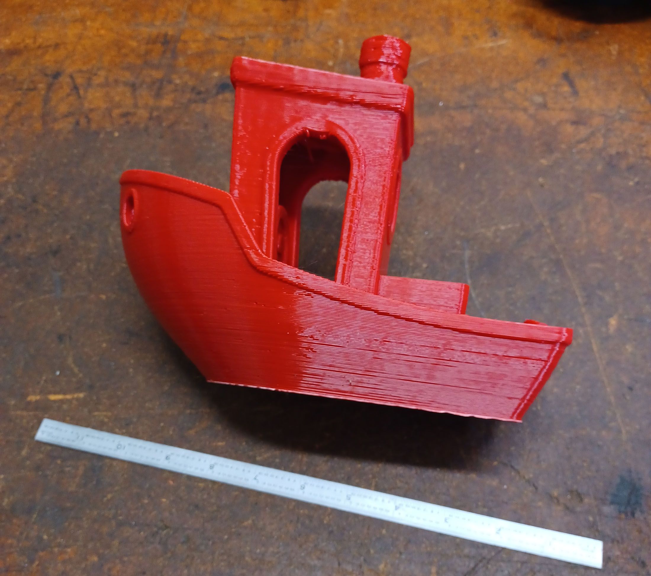
First part off the machine:

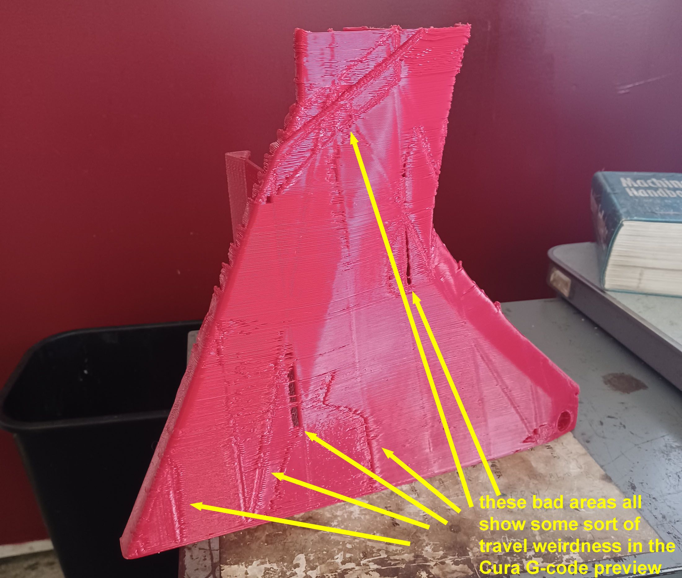
I added a couple of ribs to add stability to the part as it is being printed. There were a bunch of visible remnants on the front face, but these seemed correlated pretty well with the Cura toolpaths. In the preview there was either a start point or some change in extrusion in the problem areas. So hopefully these areas are setting related and not printer related and can be eliminated through software tweaking.
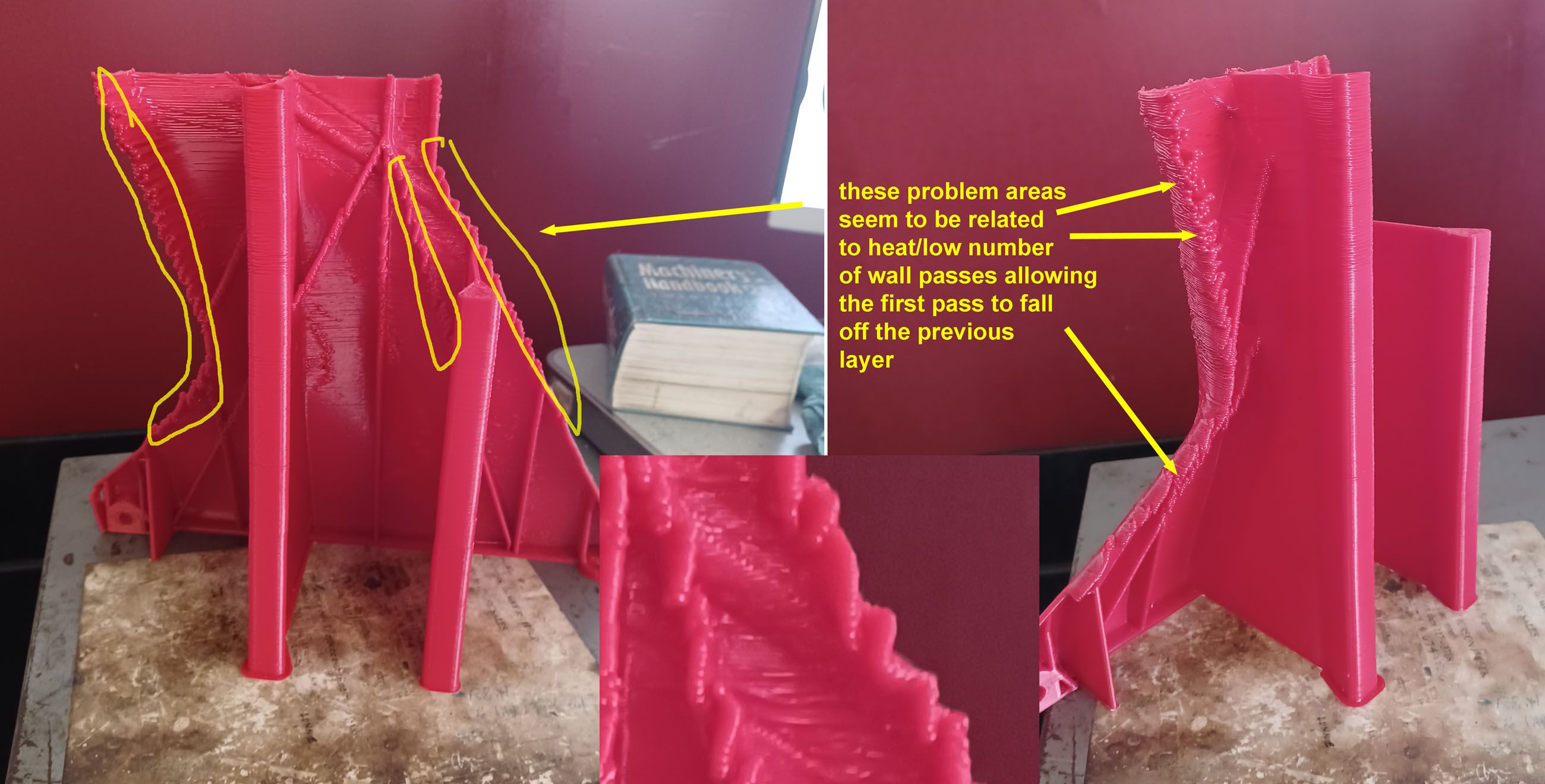
The other issue concerns thermal performance. The ends of the part and ribs seemed to be falling off the previous layer.
 This has been happening since the first print.
I think most of the problem is the overall thermal management. I noticed that with the nozzle set at 230C, the bed set at 90C, and the chamber set at 60C, once it has been printing for about 5 min the bed sensor reads 94C and the SSR that controls it never goes on. If I reduce the chamber temp to 55C, the bed temp lowers to 92C. These temps are pretty stable within +/-1.0C over time. I was very surprised at how hot the chamber heater can keep the bed, so it seems that the temps are rising uncontrollably as the part builds. On a few layers I held a small air gun at the print nozzle and manually cooled the extrusion and the bead seemed to behave better at those direction changes. I think one addition should be a layer cooling fan that turns on after 50 or so layers.
Also thinking about a smaller nozzle so that each wall is 3 passes instead of 2. Having the center bead laid down on middle of the previous layer would reduce the ability of the outer pass to sag out of position. Maybe.
Thoughts? Suggestions?
-
I've found some settings that would eliminate a lot of the small interior extrusion moves, but am having a problem in that what I thought were shrinkage remnants from the ribs is actually part of the toolpath Cura 5.0 is generating. Cura is making small moves on the surface opposite the ribs even though the STL mesh is for a smooth surface. They are clearly displaying on the G-code preview in Cura and in the printed part.

I'm not sure how to tell Cura not to do this.
-
After some feedback from the Duet3d forum before going to a smaller nozzle I'm going to try a shorter and wider print setting, 1.2mm width x 0.6mm layer height instead of 1x0.8 and see what the results are.
Chris
-
There is such a thing as beginner's luck! The first couple of prints were decent and I thought 'full steam ahead'. Then a bunch of bad prints later I needed to take a step back and try to walk before running.
 None of the slicer changes were making much of a difference to the wall quality, and even worse, I was getting sagging failures unrelated to slicer settings. So, seeing that I maybe was asking too much with the print geometry, decided to go back to square 1, a 400% Benchy, to see if the problem was the printer mechanics, the slicer settings, or the part geometry.
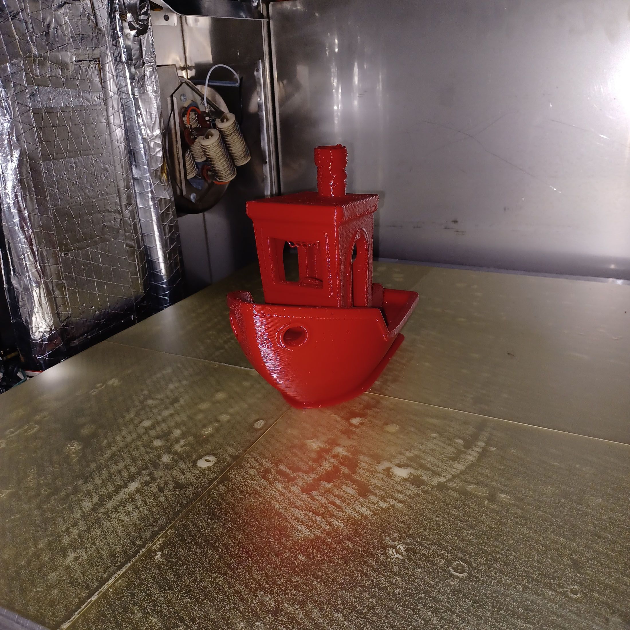
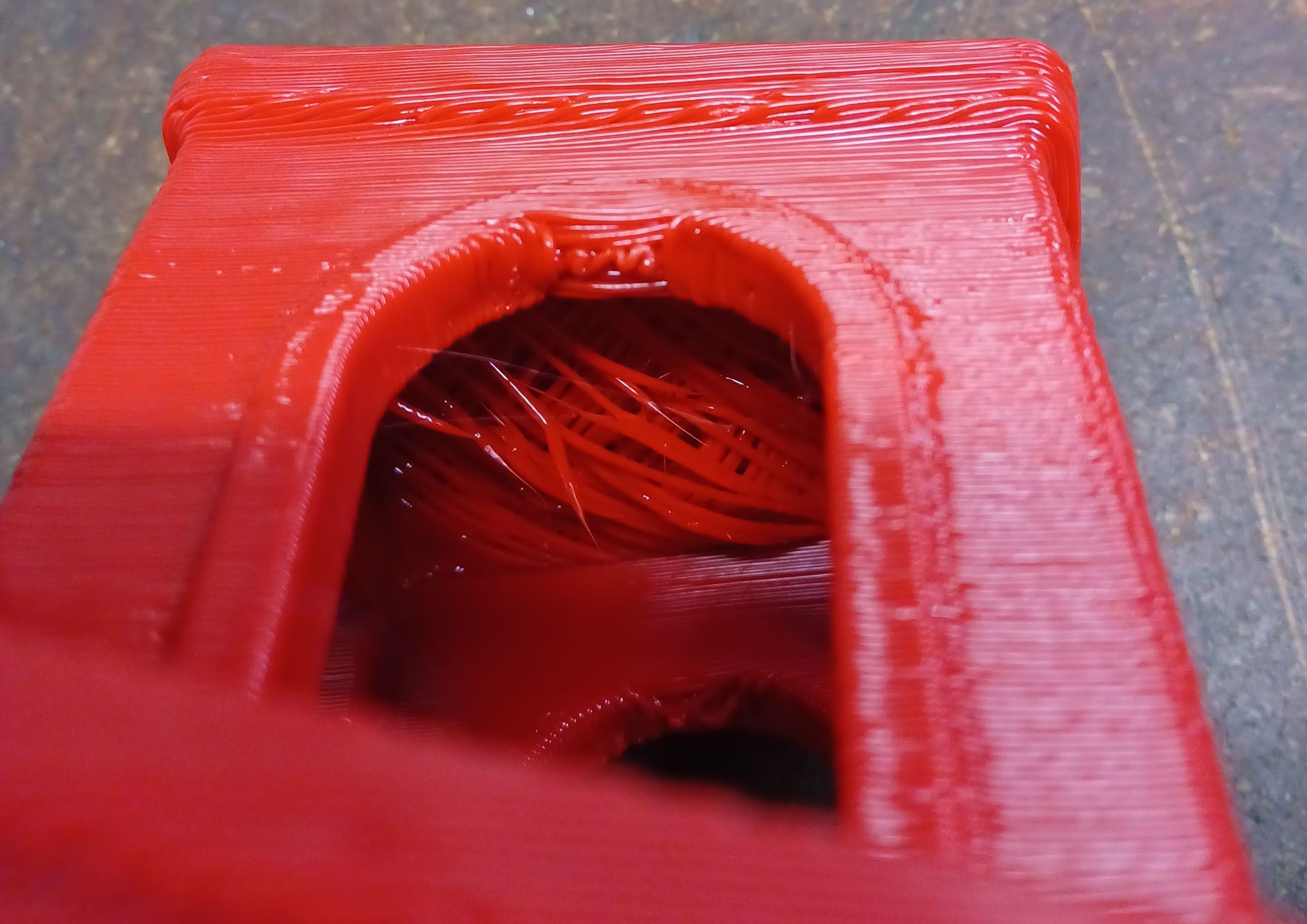
After a false start with bad print adhesion (it popped off the table after 10mm" of Z printing) It printed successfully with a 3.5hr print time at 20% infill, 1mm nozzle, 0.8mm layer height. Mostly successfully, but good enough for my purposes.The bridging on the underside of the roof started pretty sketchy, but it recovered by the top. Also there are a couple of wiggles at the top of the round window arches. These areas are not features my parts will have much of, so are not much of a worry.

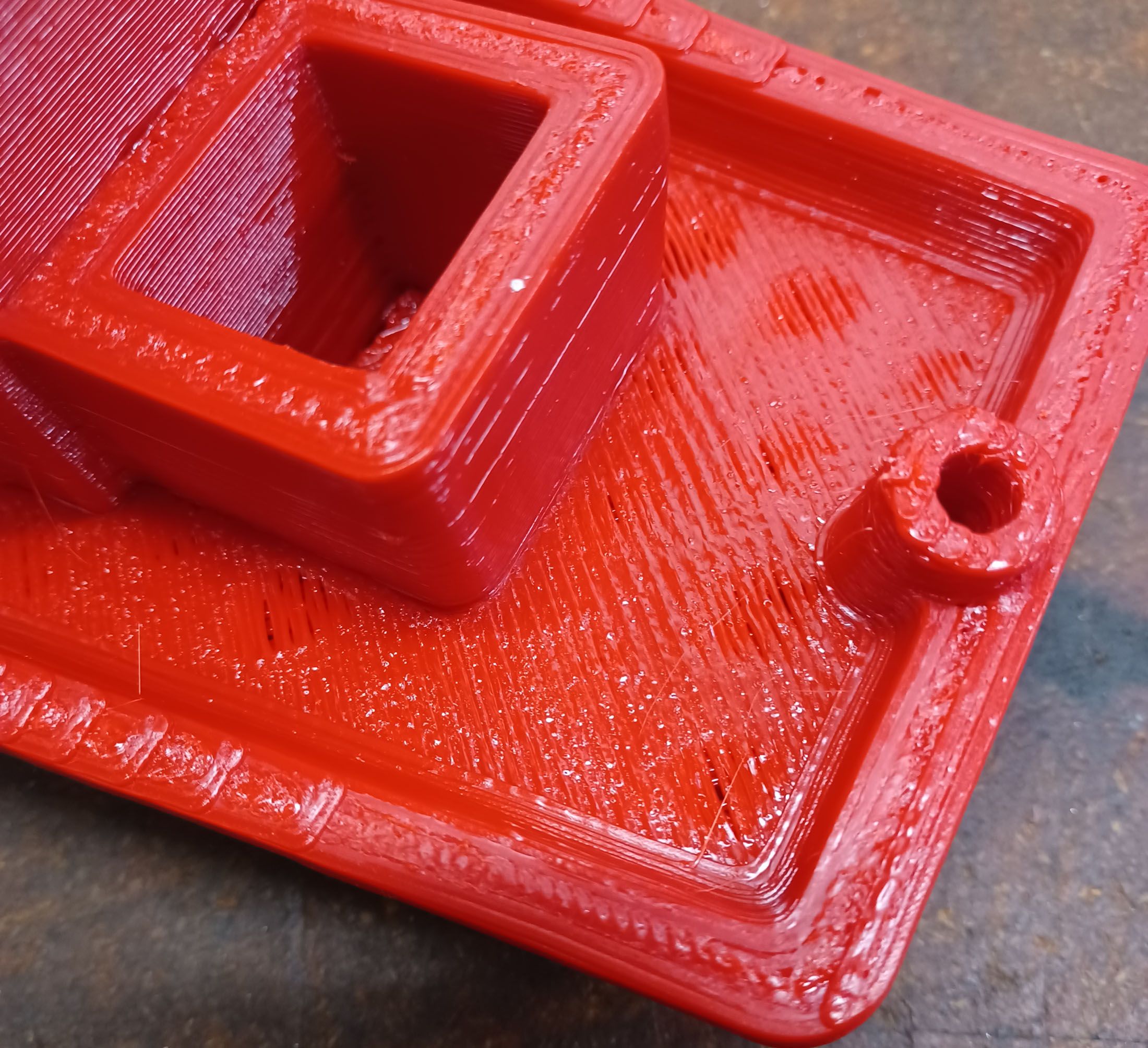
I could use another top layer, but otherwise it is flat. The chimney sagged a bit, I guess a 6sec layer time is too short.


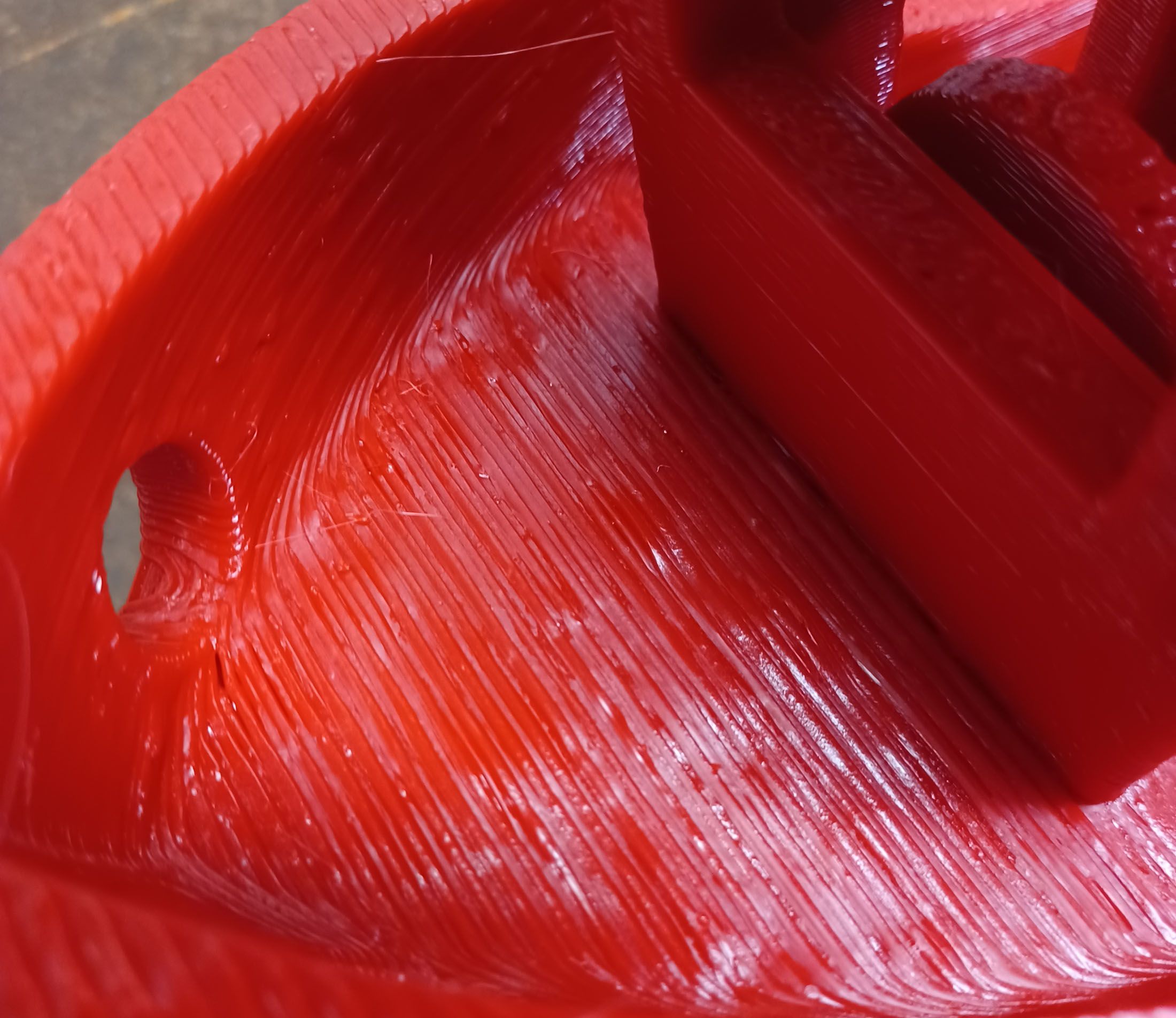
What I am interested in, the side quality, was a lot better than how the fairing parts were ending up.
 This is the quality I was hoping to see, on a surface geometry not much different that what I am hoping to print. This is heartening. The random blips match up pretty well with the random wall start points that Cura displays. Maybe I'll try 'sharpest edge' for the start point.
My main conclusion is that I am printing with too big a nozzle for the wall thickness of the fairing parts, leading to an inconsistency with how the bead is laying on the previous layer before cooling. Most of the part is a wall of 2 passes, which I guess does not provide a stable enough base to build on, especially for the slightly angled from vertical surfaces. I have a 0.8mm nozzle and will try that, and also use the Cura option 'Horizontal expansion' to offset the XY profile a bit to get 4 wall passes. If that works, maybe a 0.6mm nozzle test is in order so that the geometry does need that much post-offsetting. A smaller extrusion will also cool and solidify quicker, resulting in less sag. These steps will obviously increase print time, but better a slow successful print than a fast failure.
Chris
-
I have the loops set to 3 so there should be no infill on the large majority of the walls but there still seem to be some short segments inserted into the thin wall area.
I am picking up on the geometry tips like chamfers to sidestep overhangs, and am orienting the ribbing to minimize supports. Slowly but surely I'm getting there!
-
Thanks for the comments. There mechanicals are pretty solid without any play and the huge clearpath motors could stop the printhead on a pence so don't think it is mechanical. I had Tecnik's help tuning the stepper/servos and lots of mechanical issues can be seen through the diagnostic tools and he was pretty impressed with how good the XYUV axes were. I think the bad layer stacking alignment was due to one part of the bellows sagging when hot and rubbing back and forth on the freshly printed area. At least there was some print residue only on one area of the bellows that was above the bad area, so hopefully that is it. That area was near the chamber blower, so think the blower was blowing very hot air directly on the bellows, softened it, and it sagged and rubbed back and forth in Y on the part.
>> Zooming in to image #2 it looks like some under-extrusion is going on every few layers.
Is that caused by slippage at the extruder pinch?
>>I don't like it and it's really not good for overhangs
Agreed, I will reverse the wall printing order. Should infill be before or after walls? There is not much infill in these parts. Would setting infill to 0% or 100% be best if trying to get the part to be build using profiles only?
>>Cura doesn't support additional axes. You may have to make other adjustments.
That's what I get for making assumptions! Thought their printers were IDEX but they are just dual printheads.
>>And for that bit of advice you owe me a Vesco Rabid Transit fairing to fit a 1978 Honda GL1000 with a 7" headlight. If you want to throw in the lowers I won't complain.
These days a Vesco fairing would cost more than the bike! 😉
-
Any local experts willing to do a little paid consulting on Cura setting optimization for a custom printer? I know there a lot of guides, but there is a lot of info to review that someone with more experience than me would be more effective at. Also, I have a ton of other work on my plate at the moment!
See my post here:
Thanks,
Chris
-
Hi all, I just finished building my first large 3d printer that is intended to print prototype motorcycle fairings in ABS. You can see a lot of the details on the build at: https://forum.duet3d.com/topic/22858/new-heated-enclosure-printer
The short of it: Converted from Sigma thermal test chamber chassis. Core XY (UV soon) design using ClearPath stepper/servos and inear rails. Stepper/leadscrew Z axis. Duet3D 6HC control electronics using RRF. E3D SuperVolcano hot end with water cooled extruder and 1mm copper nozzle. 650x600x950 print volume. 120C max heated bed. 80C or so max heated chamber.
I just got the first couple of parts off the bed and while they came out decently, I think there is still a lot of improvement to be made. I'm open for any forum feedback, but if there are any resident experts that would be interested in getting paid to help me optimize the Cura 5 settings, please drop a line. The parts are mostly thin wall (.1-.15") that I would like to print as all outlines, but with the large variety of settings in Cura, do not know how to go about getting the best slicer settings.
Some of my issues are optimistic overhang estimation, but there are a lot of other problems that can likely be improved through print and machine settings.
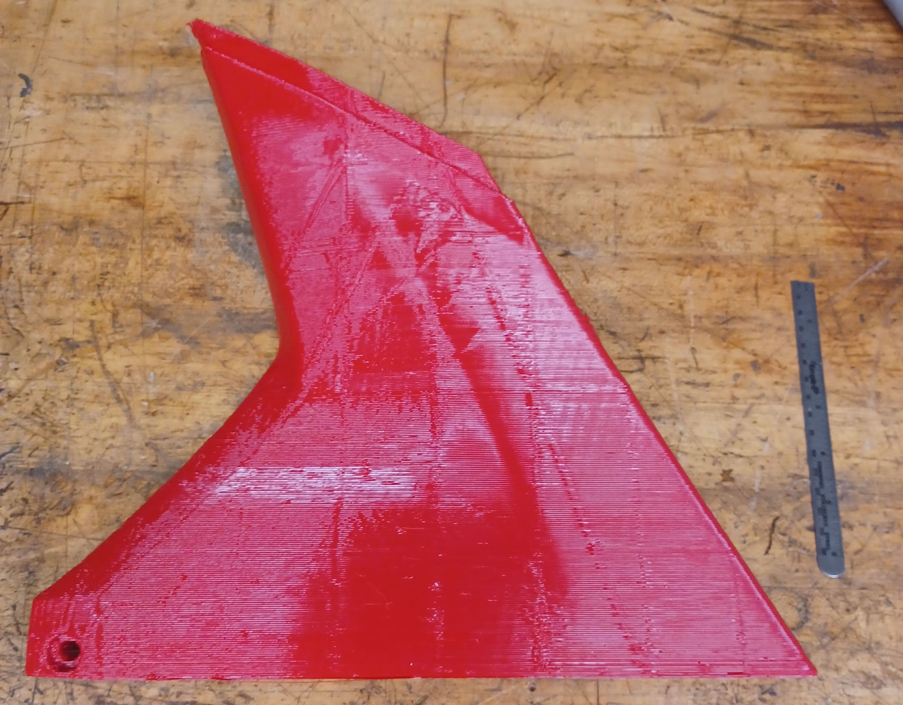
This part finished printing successfully and came out pretty good. 3.5 hr print time.


There are some issue areas that were due to optimistic overhang estimation, and some that are due to unknown issues.

Optimistic overhang, I had a thick rib at the edge of the part that was a horizontal step. I'll try to blend it in with a chamfer to angle it less.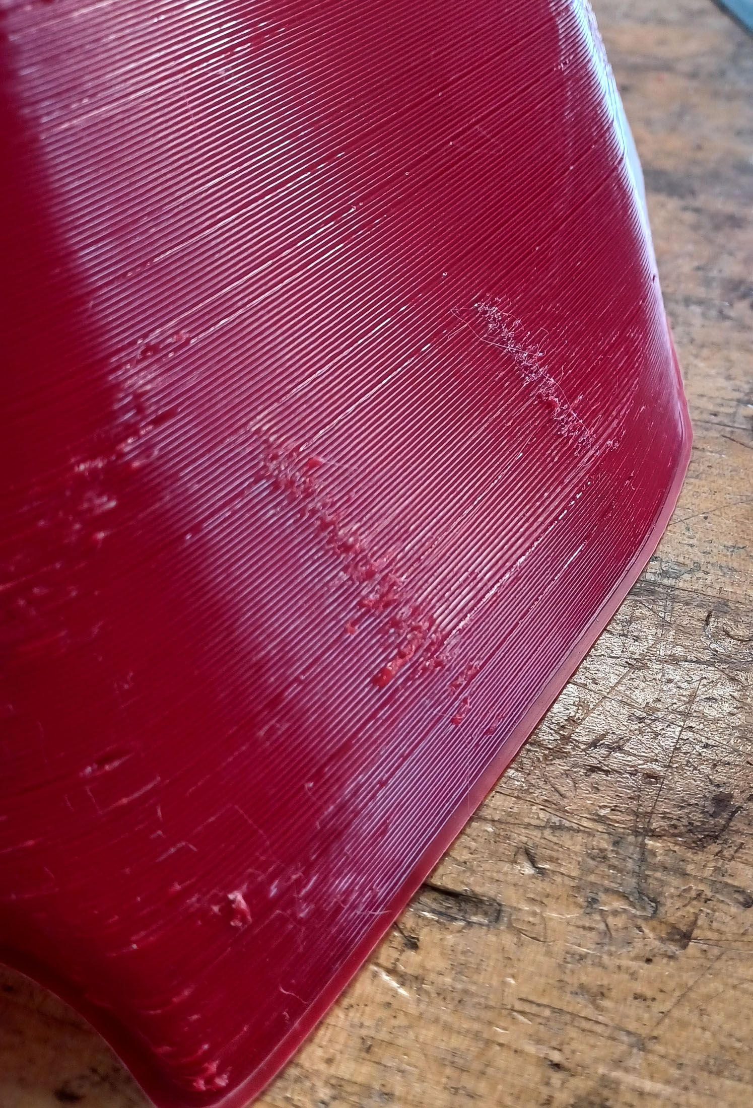
Getting print remnants on the opposite side of internal ribbing. Also some weird blobs at random places. Causes unknown.
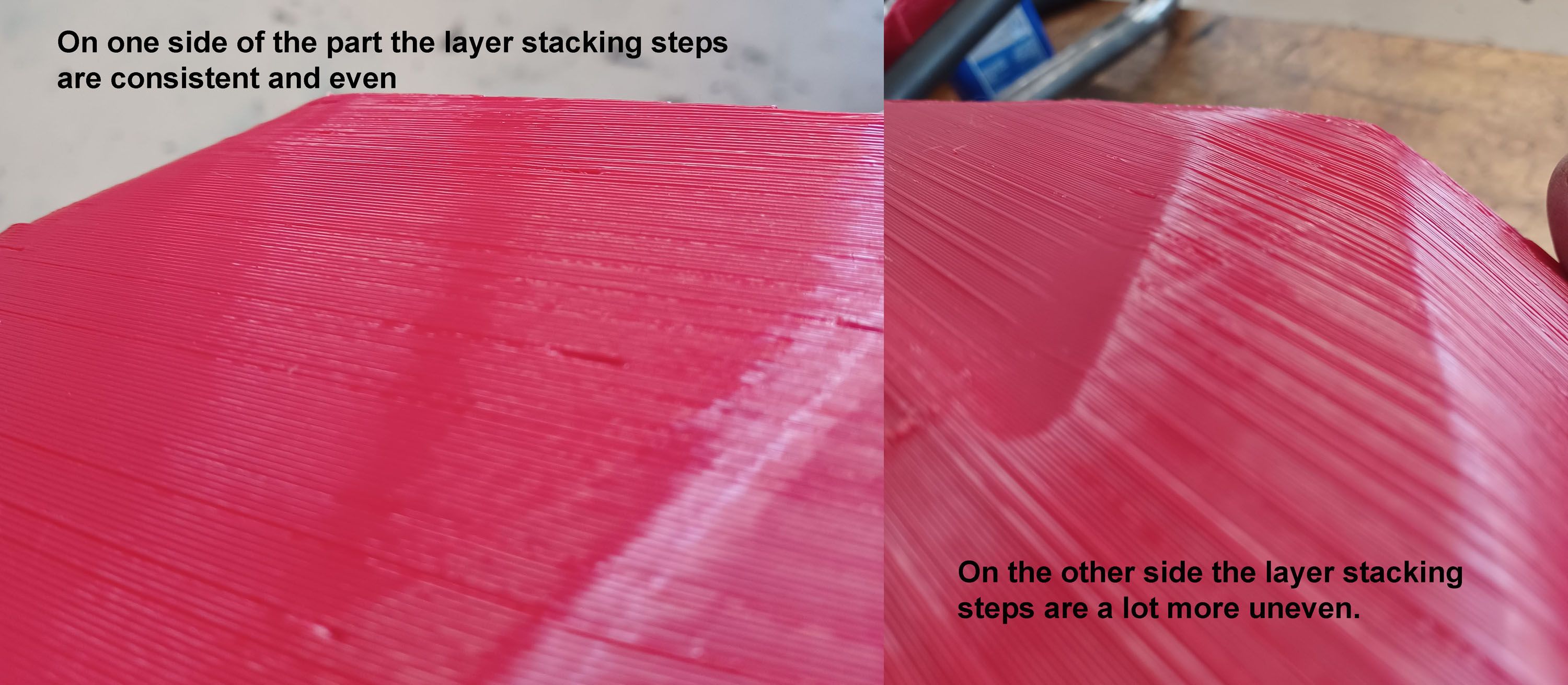
The layer stacking alignment seems to vary a lot around the part perimeter. I wonder if it is because this is only 2 or 3 printing passes and a large print bead means on the first pass the bead can fall sideways a bit. I wonder if going to a smaller nozzle and more passes would help. Or maybe in this case printing the inside pass first would help because it is centered on the previous layer instead of the outside pass first where it is perched on the edge or even overhanging the previous layer a little bit.Any comments and suggestions are welcome.
Thanks,
Chris


Trying to dial in a large DIY heated printer
in Improve your 3D prints
Posted
Also, just some little issues I'm tying to resolve:
The prints are coming out fine, but I am having one issue that requires me to babysit the first two layers. On the fist layer, the filament sometimes stops feeding. I notice it by the spool feed stepper not doing its chirp to feed. With my filament feed setup I can give a little manual push to the filament, then it starts feeding fine again. This happens 3-4 times on the first layer, then not again during the rest of the print. Each time it happens I have to blow off the pinch area because there are a lot of filament shards. Once the first layer is finished it does not happen again and as mentioned, at the end of the print the filament pinch area remains completely clean of debris.
The bed is flat so the nozzle is not getting blocked. I test it at temp using a plunge dial indicator clamped to the printhead carriage and get about 0.05mm total variance. I tried using the BL Touch for bed mesh, but was getting hugely varying scans that did not correspond to a mechanical check with an indicator. Now I just use the BLTouch for Z homing and it seems to preform repeatably and I print with no bed mesh compensation.
Also, FYI there is about 0.8mm difference in Z homing between hot and cold states.