


gr5
-
Posts
17,314 -
Joined
-
Last visited
-
Days Won
355
Content Type
Forums
Events
3D Prints
Posts posted by gr5
-
-
Okay. I won't add the Z1. But the last time I used project planner it created a blob at the very center of the print and it fell onto the bed when it went down to make the skirt and ended up getting onto the print. I just cut and sanded it off but it was annoying. I think this was because the extrusion was 6mm but the retraction was 5mm so the extra 1mm created a small squiggly mess right over the center of the print (but didn't touch down until it got ready for the skirt).
-
Oh - and to get better adhesion to the blue tape, wash it once with Isopropyl alcohol (aka rubbing alcohol) - found at any drugstore that sells aspirin and bandages. If you do that you shouldn't need to sink the bottle by 3mm.
-
You have "stringing". The simplest thing to do to reduce stringing is to lower temperature:
http://umforum.ultimaker.com/index.php?/topic/1872-some-calibration-photographs/
But be careful - you are already pretty low at 200C. I strongly recommend you do a simple test like the one I did in the above post as all PLAs are not the same both manufacturer and color. I'm told it helps to have a good quality PLA.
If you lower the temperature more you might get underextrusion which would mean you would have to lower the speed also although 50mm/sec would be plenty slow enough for me at 190C (100mm/sec would be a bit too fast for my grape colored PLA). This is also addressed at the above link.
Also you might want to add a clip: There's a blue clip on the print head where the bowden tube connects. You might want to make a similar one on the feeder. Other people seem to think this helps reduce how much you have to retract. I have one and 4.5mm is plenty for me.
Also 40mm/sec might be too fast for the retraction speed with the latest Marlin. I'm not sure - there's been discussion about this lately but I don't have the latest marlin so I haven't touched that setting.
But really I suspect the only thing you need to do is lower temp by 10C but don't waste another hour on this - do a test print first.
-
Look at your gcode. Around the 4th line you should see something like:
G28 X0 Y0
G28 Z0
The first line above homes x,y and the second line homes z. If you have this G28 Z0 already then your endstop (limit switch) is signalling already even without it being pushed. Could it be mechnically stuck? Does it click when you push on it? Remove it and the cabling from the machine. Check it with an ohmeter. It should change from infinite ohms (open) to 0 ohms (short) when you push on it. I suspect it is always shorted.
If the switch is fine, then there is something wrong with your board. Maybe a missing pullup resistor on the circuit that connects to the z endstop.
See what happens is when it goes to home the z it moves the platform up until the z trips but if it thinks the z endstop is already closed you never notice it moving up.
-
Thanks, daid. I made that change. So next time I use project planner I will be trying it.
Ooh - should the last line go to Z1 while it's at it to raise the bed?
-
I have had the same problem. I implemented a fix but haven't tried it yet as I haven't had a need to print multiple parts in a while.
Cura has start.gcode, end.gcode and nextobject.gcode. The 3rd of these I assume runs between parts for the project planner.
I changed the second to last line to reduce the extrusion. As you can see it retracts 5mm (E-5) and then later extrudes 6mm (E6). I changed the E6 to E5 (no "priming of the pump").
I also changed the 3rd to last line to "X5" so that it if it *does* extrude it will be over near the left edge instead of over the center of the object. Hopefully this doesn't result in any kind of collision when it goes to start the skirt.
Again - I haven't tested this change. You would definitely want to check the result for collisions when it goes to X5.
Move to next object on the platform. clear_z is the minimal z height we need to make sure we do not hit any objects.
G92 E0
G91                                    ;relative positioning
G1 E-1 F300                            ;retract the filament a bit before lifting the nozzle, to release some of the pressure
G1 Z+0.5 E-5 F{travel_speed}           ;move Z up a bit and retract filament even more
G90                                    ;absolute positioning
G1 Z{clear_z} F{max_z_speed}
G92 E0
G1 X5 Y{object_center_x} F{travel_speed} ;changed to x5 for left edge
G1 F200 E5 ;changed e6 to e5
G92 E0 -
MAXTEMP is 275C. If you were printing at 260C or higher I would say you should try to get your PID values better. If you were printing cooler than 260C then it is loose cable (maybe on bottom of UM).
See pictures and also step 5 on this page:
http://wiki.ultimaker.com/Ultimaker_rev.3_assembly:_Mounting_the_electronics
-
Go to step 2 here - software setup. And if you have any mechanical problems refer to step 1 - assembly. For example the last thin in step 1 talks about setting the z limit switch which is a good thing to know how to do.
http://wiki.ultimaker.com/Software_setup_guide
-
Good catch. They use the same tables, so that's great. The only difference is that the LAF is more accurate: 5% instead of the LAG which is 10%. This table probably assumes a 4.7K pullup but it doesn't say.
So now all you have to do is build marlin and change configuration.h to use temp sensor 7 as shown above.
-
If something is slipping, tighten all the set screws very very tight. To the point where you are afraid you might break something.
There are 5 set screws for each axis. Not 4. The 5th is at the motor. Tighten all 5 for the slipping axis!
-
Don't know where to find a table for that thermistor. Not all 100K thermistors are the same.
According to this:
The beta is 3974. T0=25C, R0=100000 ohms.
Knowing that you can calculate resistance at different temps here:
http://www.reprap.org/wiki/MeasuringThermistorBeta
Then calculate the needed table with this information:
http://www.reprap.org/wiki/Thermistor#Calculating_Thermistor_Beta_.2F_Rz_Values
then insert the resulting table into the Marlin firmware in the file thermistor tables.h
Then read instructions on how to build Marlin (the easiest step in tall this but will still take an hour). google "how to build marlin for arduino". Lots of instructions in many places such as here:
http://wiki.ultimaker.com/Marlin_firmware_for_the_Ultimaker
and here:
http://www.solidoodle.com/how-to-2/how-to-update-firmware/
But don't use that version of marlin. Use the ErikZalm version.
-
Just glue it back on with superglue.
-
The shaft of the motor is round (cylindrical). When you slide the pulley over the motor shaft there is a set-screw that you tighten to attach the pulley to the cylinder. But the cylinder is super strong hard. Stainless steel maybe? So you have to really tighten the heck out of that set-screw. However some people take a file and rub it carefully back and forth on one spot on the shaft to make a flat spot on the curved shaft. This is called "filing a flat".
That way if you center the set-screw on that spot it's less likely to slip.
The problem is if the screw is a tiny bit loose, everything will seem like it is working fine except you will have this extra play and when you print, your circles will be ellipses and you will think it's a loose belt and might not occur to you to check for this.
-
I'm not sure but I think it switches color every mm or so of filament which makes the colors come out kind of random. I think red is reserved for outer loops. Only the currently displayed upper 15 layers are shown proper width - layers lower than that show thin lines.
Thin "solidly blue" lines seem to show moves and thin red lines are something else - hops maybe? Anyway the thin lines are where there is no extrusion (with exception of more than 15 layers below currently displayed layer).
-
very interesting. So if we sum up all the info from those tests, for the best looking result (stringing, overhang and under extrusion) if you're not in a hurry, the best is to print at temperature around 180 C and at low speed. Right?
no and no. lol.
1) Printing at 180C is more likely to clog and worse, if your PID isn't perfect you could hit the trip point where it shuts off the ultimaker. So I don't plan to go lower than 190C. And other brand/colored PLA might not need to be so cool to not-string.
2) I'm going to do more overhang tests but I realize now that the problem with the overhangs wasn't speed so much as giving the plastic time to cool. So I'm going to print larger parts and I suspect I can print faster.
So speed might not be much of an issue for overhangs.
On parts with no stringing possible (e.g. no gaps, no towers, no retraction needed) I plan to keep my temp higher and my speeds higher.
-
It's a feature, not a bug!
I prefer it this way. It lets you see the model better. If you want to see the bottom layers you scroll the layer scrollbar to the bottom.
The feature I really miss is being able to click one layer at a time. When you have over 200 layers it's very difficult to get to a particular layer to see what's going on. I'd like to see a keyboard shortcut for going up and down one layer at a time.
Or buttons that only appear when the mouse hovers over them (to make the interface clean - like facebook does all over the place). An up arrow triangle and a down arrow triangle just like normal scroll bars.
But anytime I can do something with the keyboard instead of the mouse is a win.
-
Looks pretty good. If you print the robot a little slower he will be less droopy because each layer will have a little more time to cool. You should notice quite a difference. Or if you do the same speed but print with more infill or make him larger.
I've been thinking about adding a second fan so I can print small objects faster.
-
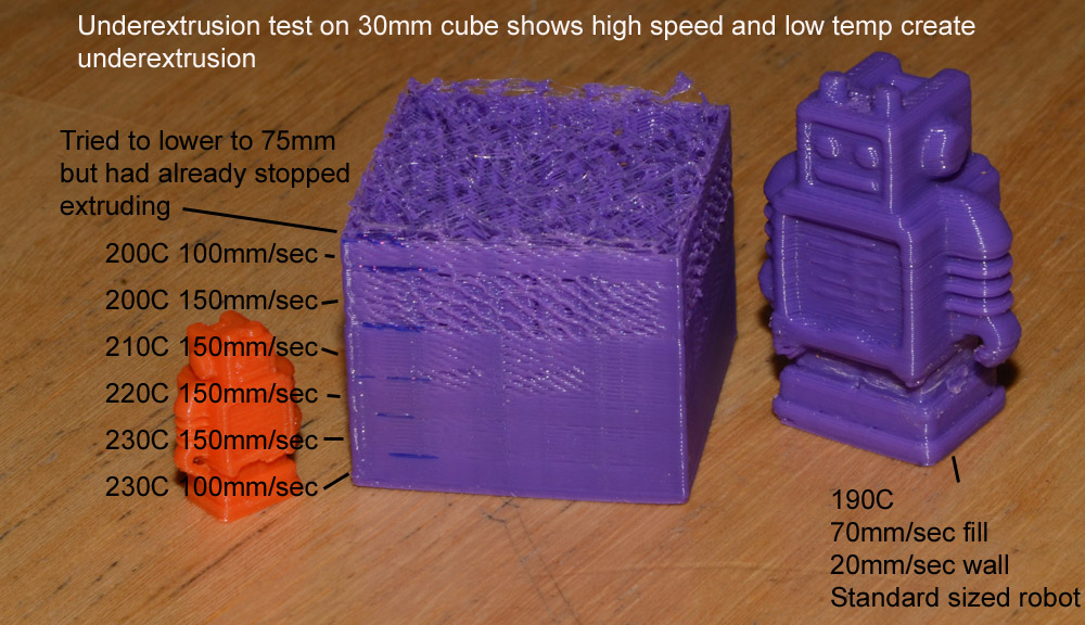
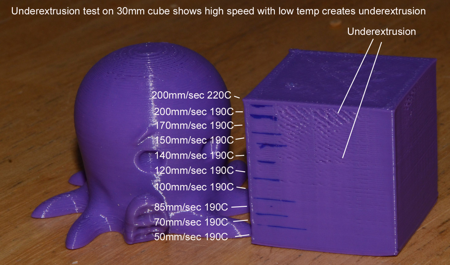
These images show the relationship between printing speed, nozzle temperature and underextrusion. Cube printed at .2mm layers.
-
 3
3
-
-
I strongly suspect the arduino has op amps on all inputs but I didn't look it up.
I doubt that 4.7K resistor made any difference either - you probably had a clog and fixed it at the higher temp and now the lower temp is working because the clog is gone.
-
Don't be afraid of building your own marlin. It's not that hard. You only have to edit Configuration.h which is 90% comments. Most of the settings are quite simple to understand and are either on/off or have values (e.g. steps_per_mm).
If you find the dual extruder marlin that comes with cura to need tweaking, just go for it. Then ask specific questions about settings in configuration.h if you get stuck.
-
Do you have windows? Did you reboot the windows machine and reboot (power cycle) the UM with it unplugged from windows?
When you plug the USB cable into the UM do you hear a sound from windows (guh dump)?
If you go into device manager on windows does it show a new com3 device called "arduino" something? Under printers/com ports or some similar category in device manager?
-
Ultimaker is a business so I assume they prefer to keep their parts list obscure. What you are doing may be bad for the company. Not sure how they feel about this.
-
Glad that worked.
Consider also doubling the wall if the part doesn't seem strong enough. Your nozzle diameter should be .4mm so 2X that would be .8mm so consider making the walls .8mm which is two passes around. That will give you more strength without hurting print quality too much.
Or try a different infill pattern - hex instead of lines.
-
Did you consider checking the resistance when it is hot? Most resistors change their resistance significantly as you heat them.
It's good for a heater to *increase* it's resistance as it gets hotter - for self regulation, safety, and faster warmup.

Optimal Manual Settings
in UltiMaker Cura
Posted
What Illuminarti said. That's what I wanted to say.
That space under your print bed - it's purpose is to keep a notebook with notes on every print you ever do so you can go back and say to yourself "what did I do different on this print that it came out so well?". Or "so poorly".