


SyntaxTerror
-
Posts
575 -
Joined
-
Last visited
-
Days Won
20
Content Type
Forums
Events
3D Prints
Everything posted by SyntaxTerror
-
That's because you're looking at Vcesat max, and it's measured at Icm, which is the peak collector current, 1A for this device. At 300mA you're looking at Vce < 200mV
-
Ah, I wouldn't worry about Trump, he knows what to do. Give it a few days and he'll be on twitter claiming it was Obama who caused Ultimaker to file a patent. Or fake news Oh yeah And afterwards there'll be a press conference where Spicer tells us this patent is the worst patent ever. Period.
-
If only life was so simple. 500mA is the maximum power. However, the true limitation is power dissipation. As there is no active cooling, your true limit is heat based. For that you need to calculate the amount of power "spend" in the transistor, and know the thermal properties (some of which are in the datasheet, some are "defined" by the board), the maximum temperature allowed by the transistor and the ambient temperature. True, but the power dissipation in the transistor should be minimal due to it being PWM driven and ideally in a fully on or fully off state at all times. In the ideal world, the transistor should be run saturated and responsible for a 0V drop collector-emitter.
-
Ah, I wouldn't worry about Trump, he knows what to do. Give it a few days and he'll be on twitter claiming it was Obama who caused Ultimaker to file a patent.
-

UM2+ for ABS - perfect printer?
SyntaxTerror replied to brunbjoern's topic in Buying or selling your UltiMaker
I think you made a good choice. There's always grumbling about the price, but very few people who have prior experience with 3D printers wind up disappointed by the UM2+. I bought one. Played around with it for a couple of months getting happier and happier with it. And then I bought another. So watch yourself Also, forgive me for prying... I know your location says Germany but are you somehow related to Scandinavia? -
UM2+ for ABS - perfect printer?
SyntaxTerror replied to brunbjoern's topic in Buying or selling your UltiMaker
It's easy to get confused reading other people's opinions of various 3D printers. But in all fairness, it's rather difficult to compete with the UM2+. At least at this price point, even if it is expensive. It is a mature and reliable machine that produces high quality prints. It's as with any other product. Opinions vary. Yes, there are printers that produce better quality. Yes, there are more reliable printers. Yes, there are cheaper printers. Are there any that can truly claim to have it beat on all three points? If we put on the eyeglasses of neutrality - it's doubtful. There are some that are at least comparable. I will say that whenever you hear someone claiming they have the Ultimaker beat by miles at a much cheaper price point (like it seems trendy to do some places on the internet), I reserve the right to call bullshit. There are many other excellent printers out there though. I've heard several people raving about the Zortrax M200, for instance. No doubt a solid printer. I hear it's very, very good for ABS printing. High quality prints, apparently very reliable, cheaper than the UM2+. I still wouldn't touch it with a 10 foot pole because of the closed ecosystem around it. I want versatility and hackability. I want to feed it whatever odd filament I stumble across. But that's just me. You say you want ABS because your prints must survive elevated temperature. ABS is just one such choice. As neotko mentioned, there's PLATEC. I've been playing with ASA quite a bit too. Both of which don't stink up the house -
Well I like to err on the side of caution
-
If your bearings are indeed making that grinding sound like they're lubricated with gravel, stop printing immediately and replace them before you end up needing new rods as well. The whole thing might well be caused by a bearing that refuses to slide like it's supposed to.
-
Discussion is good, and emotional outbursts are bound to show up from time to time whenever there are passionate people involved. I don't consider that a problem; people are pretty well behaved in here as well. But I still think wisdom would be to hold the doomsday predictions until empirical data exists to back them up.
-
Well, we haven't fixed anything yet The ISCP headers are what you use to upload firmware directly to the micros directly. Most Arduino people have been in contact with those at one point or another, I'll bet. Arduinos of course are cheap and readily available, and make for excellent ICSP programming interfaces. Computer --[uSB]--> Arduino --[iCSP]--> device to program. I'm hoping someone who's had an unresponsive USB interface can lend us a bit of experience. The microcontrollers run off the 5V rail, so barring any unexpected supply noise or burnt tracks on the board, they should be good to go.
-
Well, I can't be sure that's the case. But at this point in the troubleshooting, it would certainly serve as my main suspect. You can spend untold hours looking for a hardware problem when in reality the microcontroller just insists on mismanaging the peripherals. I would most definitely attempt to get fresh firmware on both microcontrollers before doing anything else. Since you can't connect and upload firmware via Cura, it looks like you'll have to use the ISCP headers on the main board to upload it. That's where my experience is pretty much zero - never did it on the Ultimaker. I'm hoping someone with experience could help out here? As for programming adapters, an arduino usually works very well for this sort of thing if you have access to one.
-
Well, I think the display is dead not because of lack of power but because it's not receiving anything to display. I'm working from the observation that the PC won't interface with the microcontrollers, which we've determined should be under power. Like an arduino, the ATMEGA 16U2 should provide a USB interface to the ATMEGA2560 and we should be able to communicate with the printer. They should start up when the power switch is closed, and you should be able to connect. If the problem was with the display itself, the USB connection should be unaffected. I think the right thing to do right now is try to ensure the microcontroller firmware isn't corrupted. As most people with the 16U2 equipped arduinos can attest to, they're just not as stable as the older FDTI equipped ones. The display itself is powered by 3V3 (VDD) and 13V (VCC). The former we've already checked, the latter is only available on the controller board. It's created from a boost converter on the 5V line and only used by the actual display. It's available on TP5 (on the controller board, not the main board) should you want to measure it (be careful removing the cover, it holds the display in place). I'd probably leave it alone though, my suspicions lead me elsewhere.
-
Me too - I can't see what gives anyone valid reason to lose trust at this point? I think that train of thought is unfair. Let's stay calm and give Ultimaker the benefit of the doubt here; if they enforce said patent in an unfair way, then by all means, complain away. Right now I'm seeing a guy walking out of a gun shop with his new hunting rifle, and people accusing him of making plans to blow away an entire kindergarten somewhere.
-
As much as I dislike the concept of patents and intellectual property, I understand Ultimaker's reasoning here. I for one am not going to rush in and judge Ultimaker for what they might do with a patent.
-
This is all very strange. I think we can safely conclude you have somehow suffered two separate problems at the same time. The 24V adapter is working, the 5V buck converter is working, the 3V3 regulator is working - the only supply line we haven't checked is from the 13V boost converter on the controller board. Given that the printer refuses to connect with the computer, it's probably nothing to do with the display anyway. The fan issue must obviously be a problem with either the extension cable or the fan itself. The power is there, so. I'm betting on the fan, it's probably just dead. The hot end fans lead a rough life. If the 5V supply is up, then both of the microcontrollers should be doing something. I'm thinking maybe the next logical step is to try to feed the printer some new firmware through ICSP? I've never had reason to do so myself, and I know there are a bunch of pitfalls there - maybe someone has a fail-proof method?
-
Pin 1 is 5V and pin 2 is GND on both J22 and J34, so there won't be any difference between the two. I'm thinking maybe the colors of the extension cable wires has you confused like it did me? On both my UM2 and my UM2+, the hot end fan terminates in a JST connector that mates with the onboard J34.
-
Now that is an intriguing and mysterious result.... most unexpected. So, the power supply appears okay, we have 24 volts in. The buck converter appears to be working, delivering 5 volts. Yet the hot end fan is not moving and the display is dead. The hot end fan being dead is somewhat odd. I can't see any other possibilities than either the fan is dead or the wire loom has a defect somewhere. I expected absence of 24 or 5 volt supply since the fan was not moving and there's no signs of life on the display. Since 5V presence is now verified, I'd go one step further with the test points and check the 3.3V regulator as well, at TP17: Next, I think the right thing to do is unscrew the hot end fan from the print head. Unplug it from the wire loom extender cable and plug it directly into the main board fan connector. If it starts running then, we know you have an open circuit in the wire loom to the print head. No matter what happens, for the fan you should just use J34 instead of the serial header, that's what it's there for. We might as well get that corrected. Hooking the fan up like it is on your printer makes no sense. As for the apparent unresponsiveness of the printer, you should try plugging in the USB cable and firing up Cura. See if it can connect with the printer.

-
Actually, it IS me who's not remembering things right. On the hot end fan, the blue wire of the extension cable connects with the red fan wire, and the orange wire goes to black. I think I might be damaged by my education. When I see blue, I can't help thinking neutral. And with the gear I work on every day, blue is pretty much always 400Hz AC cold. So my disposition is just wrong The hot end fan connector is correctly installed. But in a strange place.
-
In the wire loom going to the print head, the model fan wiring is Red --> Yellow and Black --> Green. It should also be impossible to swap, as the connectors are keyed and will only go in one way. So that part looks correct.
-
Yeah that's for sure I'll have a look at my own printer when I get back home and see what connects to what. In the mean time, @shurik , have you given up on fixing the board?
-
Well, it could be me not remembering what's what correctly. To be honest I've had enough versions of what's what on the hot end fan connector lately, if you know what I mean
-
Yeah that is very odd isn't it? Also I can't wrap my mind around why the polarity is like it is. Pin 1 is 5V and pin 2 is GND on the serial header, according to schematics.
-
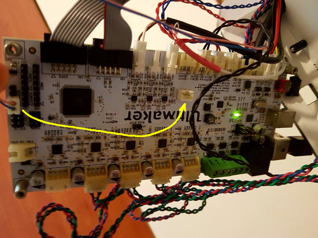
Alright, as I said I think it's prudent to check if you have supply voltage before drawing any sort of conclusion. So hook up your board again and flip the power switch on. This is the copper (back) side of the board: Get your multimeter out, set it to measure DC voltage. Your common measuring pin goes on TP24, which is a ground. Then measure the test points for the fan and look for 24 volts DC. I can't remember which one it is - the silk screen with the test point numbers has an error on this board. One of the two should read 24 volts though, if your power supply is working and the power switch is closed. If you can find this voltage, move on to measure TP16 next. That's the 5V output from the buck converter.

-
It's not at all unlikely. I'd still start off verifying that the buck converter actually has 24V input before firing up the hot air rework station though. Thanks for clearing that up! I'm way too new to know about all the little changes over the years True, it would not kill the printer - but it wouldn't run either so I'm just wondering what's going on.
-
Perhaps because the connector pins are swapped at the plug? If you compare it with the documentation: black is now at the +5V side, and red is ground...? Oh 3 years old... But that means that the short circuit could have damaged any part of the board right? Edit: I see @electromu reply now... I think you guys lost me now. I'm seeing a black wire on pin 1 and a red wire on pin 2 of J22. The 2.1.1 main board schematics want that to be the other way around? Is the extender cable pins swapped, you mean?


