


XYZDesignPro
-
Posts
288 -
Joined
-
Last visited
-
Days Won
5
Content Type
Forums
Events
3D Prints
Posts posted by XYZDesignPro
-
-
So, based on other comments I've seen on this forum, I'd say your outer diameters are about as good as you're going to get. I mean less than 1% error ( actually 0.7% ) is pretty acceptable in my world. Likewise, the height error is only 0.3%. Again, pretty much an acceptable variance in my world.
The I.D. is somewhat adjustable using the "Horizontal Expansion" setting. This has been discussed elsewhere on this forum.
I'm sure someone will more knowledge than I will jump in here at some point.
-
I would think CPE or any PETG filament would be fine. If the loads, as you say, are indeed all compression even PLA would be OK. As far as the long tubular parts are concerned, why not just use schedule 40 PVC pipe, or extruded aluminum tubing?
-
Most of the settings for support are hidden by default. Support Density can be found if you check the box under the Preferences > Setting Visability

Also be sure your Print Core 2 is well primed.
-
I'm using the one you posted on 11-9 .
CuraSolidWorksPlugin-v4-2018-11-07T20_26_08Z.curapackage
Not the one from the Toolbox (Marketplace). What package am I supposed to be using?
-
I installed 0.5.6, on Cura 3.4.1, but I saw no difference in the interface. I was expecting a dialog box allowing me to adjust the resolution, but it did not. Just acted the same as 0.5.5. The Plugin toolbox indicates the 0.5.6 is installed.

Any suggestions?
-
I have downloaded CuraSolidWorksPlugin-v4-2018-11-07T20_26_08Z.curapackage
How do I go about installing it?
-
The link takes you to the plugin for SCAD
CuraSolidWorksPlugin-v4-2018-11-07T20_26_08Z.curapackage

Help??
-
Got it.
Thanks for all of your work on this Thomas. I may have an opportunity to test it out over the weekend.
-
 1
1
-
-
Of the two, which one is the correct one to use with SWX 2018 running on Windows 10 Pro and Cura 3.4.1?
-
Thomas,
Sorry for not jumping in here sooner. Had a project that had to get out by Monday.
Where can I download 0.6.0 to try it?
-
Sorry Thomas. I don't understand the question. As you can see, changing the units has no bearing on the deviation value.


What am I missing?
That said, I really like the look of the UI . . .?
-
Cool . . . ? I am still using Cura 3.4.1 because 3.5 .x was / is so broken. Will the new version be available through the Toolbox Plugin checker?
Let me know if you're looking for a tester. I'm on Win10 Pro, SWX 2018.
-
Interesting. I had no idea SketchUp would even read an STL file. Anyway, wouldn't it be just easier to have the architect send you the files in a more usable format?
-
-
Welcome back from your world travels. Hope you at least did a little sight seeing and relaxing . . .
Thanks for the update Thomas. Cura 3.5 is so "buggy" I have un-installed it and continue to use 3.4.1. Your plugin V0.5.5 works just fine in Cura 3.4.1. What is the new version number of your plugin, and what improvements were made?
Cura 3.5 was not ready for prime time IMHO. Pretty disappointing. ☹️
-
1
-
-
SolidWorks plugin no longer works with Cura 3.5

Fails both from inside Cura 3.5 when opening a SolidWorks file from the Cura File menu as well as from inside SolidWorks using the Cura macro. Worked fine in Cura 3.4.1
SolidWorks 2018 SP 4.0, Windows 10 Pro
-
SolidWorks plugin no longer works with Cura 3.5

Fails both from inside Cura 3.5 when opening a SolidWorks file from the Cura File menu as well as from inside SolidWorks using the Cura macro. Worked fine in Cura 3.4.1
SolidWorks 2018 SP 4.0, Windows 10 Pro
-
I must say Giovanni you peaked my interest with your cube measurements. I print most objects much larger than your cube but sometimes smaller threaded objects (neck finish of bottle) where a cap must be screwed on, and I never see the kind of variation you have described. Here are photos of a cube I printed that is .875" (7/8") on a side. I chose that size arbitrarily, but it is close to your cube. The Z is only off target by .0035" (0.09mm), and while the X & Y are some .012 (0.3mm) larger than the target, they are within .0015" (0.04mm) of each other.

Z Axis.

Y Axis.

X Axis.
Settings:
.4 Nozzle, .2 Layer, Print speeds, outer wall 20mm/s, inner wall 30mm/s, 15% infill (Lines) Wall Jerk 3mm/s, travel speed 125, Print & Travel Acceleration Speeds 2000mm/s. Generic PLA at 205°
As you can see I print pretty slow. I find accuracy is quite dependent on speed
I don't think you can expect results much better than these figures from an FDM printer. Hope this gives you some insight into the capabilities of the UM3.
-
Here's what 3D Systems has to say:

So I guess if it will run on Windows 8, it should be OK on Windows 10. The trial is a free download. What have you got to loose?
-
I was not aware that the project was designed to be a printing challenge. Also I had no idea the parts could not be separated, for post printing assembly, for some unapparent reason. I was thinking more along the lines of good DfAM. While I have a UM3 Ext, and I assume you do as well, not everyone has the ability to print with dis-solvable PVA supports. Printing this part without that ability would be a real mess IMHO.
As smartavionics said earlier: 3d printing, it's a tradeoff
Anyway, just my 2¢ worth . . .
-
I have always been under the impression that single extrusion increased / maximized the build area of the UM3. There is a profile available for the UM3 for single extrusion:
https://ultimaker.com/download/59981/MaxVolume-UM3_PLA (Single extrusion).curaprofile
Maybe this will help?
-
I would print the part in 3 pieces. Top and bottom plates with a hole the diameter of the connector rod, and the Rod itself. Press fit or glue the assembly. Might need to use a brim on the connector rod. Print the two plates first and get the actual hole diameter that the printer produces and then experiment by printing a short section of the rod until you get a good fit. Then print the whole rod. No support material required.
-
1
-
-
Not as far as I'm concerned. I'm used to working with either unit. Can't speak for AbeFM
-
1
-
-
Sorry, I guess I mis-understood what you were asking for. How about these?

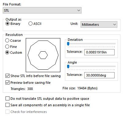
It would appear that the Max settings are the same as the default Coarse setting.
-
 1
1
-


Large print Requires more material than available on spool
in Improve your 3D prints
Posted
Happy New Year kmanstudios. I think you meant it didn't (wouldn't) suck!!👎