Jump to content

Use EXP3 pinout / 6 PWM


noctis

Recommended Posts

Posted · Use EXP3 pinout / 6 PWM

Hey folks

I want to use the EXP3 (PWM) pins to control an Ikea Dioder RGB LED bar, but don't know if I can do so.

The pins.h from github/ErikZalm are already used for:


#define HEATER_BED_PIN 4
#define TEMP_BED_PIN 10
#define HEATER_0_PIN 2
#define TEMP_0_PIN 8 //Is this Pin A8 or just 8???
#define HEATER_1_PIN 3
#define TEMP_1_PIN 9 //so why is this Pin used, when the PCB Wiki tells me its on EXP3?
#define HEATER_2_PIN -1
#define TEMP_2_PIN -1 //What does -1 mean?
#define E0_STEP_PIN 43
#define E0_DIR_PIN 45
#define E0_ENABLE_PIN 41
#define E1_STEP_PIN 49
#define E1_DIR_PIN 47
#define E1_ENABLE_PIN 48
#define SDPOWER -1
#define SDSS 53
#define LED_PIN 13
#define FAN_PIN 7
#define PS_ON_PIN 12

I'm trying to attach the IKEA RGB Dioder LED bars to Marlin. I've already solderd a Darlington array with an step-down board and tested it with my 2nd Mega.

It's working with pin 8-13 - so far so good.

Also the custom G-Code M250 (all off) M251, M252 (on) are working with Marlin.

But as told, I need 6 channels.

Can someone show me a solution to get 6 PWM outputs or one Tx (with arduino micro)? I'm totally stucked in code.

Thanks a lot!

Greetings, Noc


  • Link to post
    Share on other sites

    Posted · Use EXP3 pinout / 6 PWM

    This would be awesome. I already have a Dioder set installed on my machine with just the included controller hanging out the side. Never even thought of trying to control the colors with the Ultimaker itself.

    Hope you figure this out, good luck man


  • Link to post
    Share on other sites

    • 1 year later...
    Posted · Use EXP3 pinout / 6 PWM

    Any luck with this? Even just 3 PWM outputs would be okay I think, and just use the controller that came with the unit as a base, like this

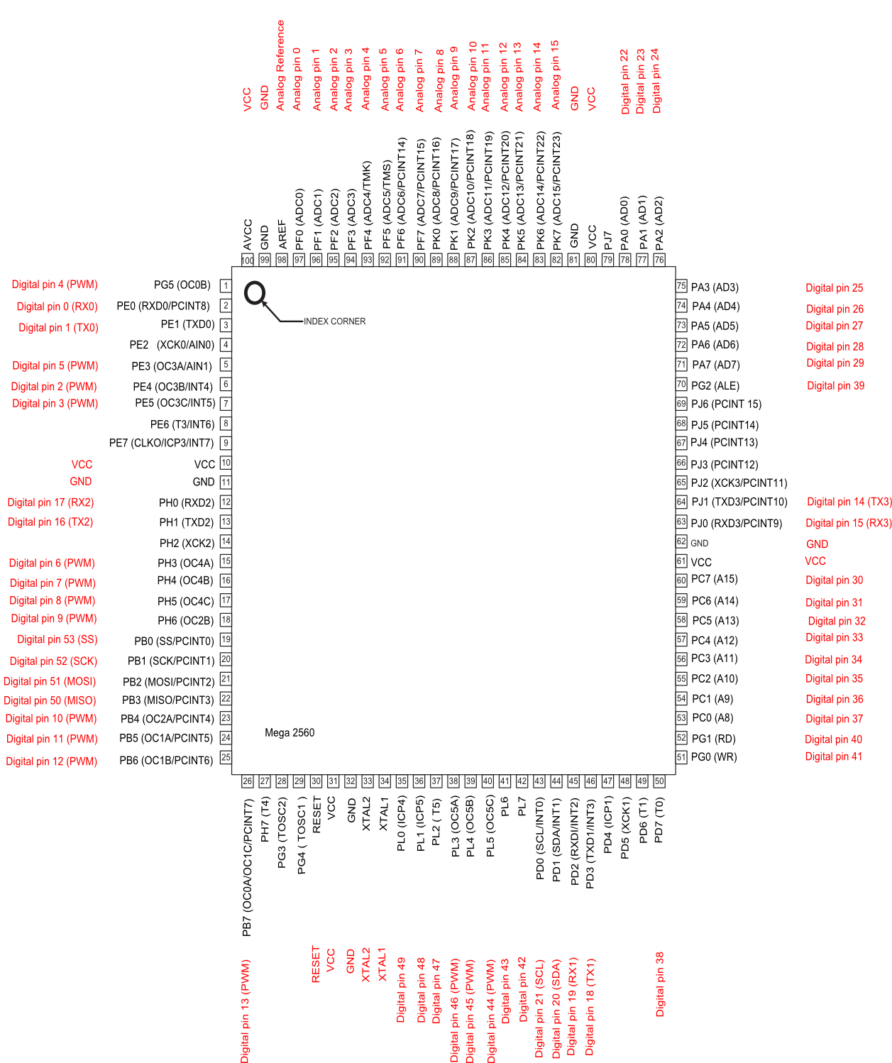
    Looking at pins.h it looks like only pin 11 is free is you're using 2 extruders and a heated bed though, so this might not be possible. Maybe the LED_PIN (13) could be used but I'm really not good with this kind of stuff


  • Link to post
    Share on other sites

    Posted · Use EXP3 pinout / 6 PWM

    Thanks for clearing that up.

    This is going to make me sound like a noob but I figured I should ask before I let the smoke out on something.

    So according to this diagram here: http://arduino.cc/en/uploads/Hacking/PinMap2560big.png

    EXP3 on the UM PCB (1.5.7) would be digital pins 8-13, AKA actual pins (according to the diagram) 17, 18, 23, 24, 25, and 26?

    And all of these are free to use as I/O? I plan on using the M42 command to play with these, would I use "M42 P13 Sxxx" or "M42 P26 Sxxx" to address the LEDPIN?

    I am quite new to arduino/electronics in general if you couldn't tell, sorry to ask a million questions.


  • Link to post
    Share on other sites

    Posted · Use EXP3 pinout / 6 PWM

    Alright, so I've sort of got this working, but it acts funny.

    R, G, B channels hooked up to pins 8, 9 , and 10 respectively on EXP3. Setting all to 255 ("M42 P8 S255", "M42 P9 S255" ...) gives me white as expected. Setting to 255, 0, 0 gives me orange when I expect red, and setting to 0, 0, 0 gives me green which I expected to have the lights turn off. Green is the default, ie. that's whats on before giving any commands after plugging the printer in. I also got this green effect running the controller off a standalone arduino. Any ideas what's going on?

    Working on a Cura plugin now, but I would like be able to fade these LED's through all their colors. I'd imagine I'd have to put this in Marlin somewhere to avoid a never ending G-Code? Might as well try and add a menu for the LCD controller while I'm in there. I don't know Python or Arduino very well so this will be a process.

    Here's some pics, basically hacked up the controller just like that video a couple posts up.

    LED controller

    LED controller


    • Like 1
    Link to post
    Share on other sites

    Create an account or sign in to comment

    You need to be a member in order to leave a comment

    Create an account

    Sign up for a new account in our community. It's easy!

    Register a new account

    Sign in

    Already have an account? Sign in here.

    Sign In Now
    • Our picks

      • Introducing Universal Cura Projects in the UltiMaker Cura 5.7 beta
        Strap in for the first Cura release of 2024! This 5.7 beta release brings new material profiles as well as cloud printing for Method series printers, and introduces a powerful new way of sharing print settings using printer-agnostic project files! Also, if you want to download the cute dinosaur card holder featured below, it was specially designed for this release and can be found on Thingiverse! 
          • Like
        • 10 replies
      • S-Line Firmware 8.3.0 was released Nov. 20th on the "Latest" firmware branch.
        (Sorry, was out of office when this released)

        This update is for...
        All UltiMaker S series  
        New features
         
        Temperature status. During print preparation, the temperatures of the print cores and build plate will be shown on the display. This gives a better indication of the progress and remaining wait time. Save log files in paused state. It is now possible to save the printer's log files to USB if the currently active print job is paused. Previously, the Dump logs to USB option was only enabled if the printer was in idle state. Confirm print removal via Digital Factory. If the printer is connected to the Digital Factory, it is now possible to confirm the removal of a previous print job via the Digital Factory interface. This is useful in situations where the build plate is clear, but the operator forgot to select Confirm removal on the printer’s display. Visit this page for more information about this feature.
          • Like
        • 0 replies
    ×
    ×
    • Create New...