


anon4321
-
Posts
914 -
Joined
-
Last visited
-
Days Won
1
Content Type
Forums
Events
3D Prints
Posts posted by anon4321
-
-
I think the drivers were originally done by pololu and then copied many many times. They have distributors in Russia:
http://www.pololu.com/distributors#russia
These are compatible with the ones that come with the printer:
http://www.pololu.com/product/1182/
You can upgrade to the black version which handle more current or the DRV8825 which handles even more current.
http://www.pololu.com/product/2128
http://www.pololu.com/product/2133
The upgraded versions are both pin compatible with the first one and those in the printer. However, the DRV8825 version defaults to 32 microsteps whereas the original and black version default to 16 microsteps. For the DRV8825, you need to alter the jumpers on the shield so that it is in 16 microstep mode or update the firmware steps/mm.
However, for any of the three pololu supplied drivers, you need to solder the pins/headers on and they do NOT come with a heatsink. You can use pliers to remove the heatsink off the driver you are replacing and then scrap and clean and then use a thermal adhesive like http://www.arcticsilver.com/ta.htm to attach to the new driver.
With all that aside, the question is why is the driver shutting down? Did you check that the stepper is free and easily moved after removing the filament? can it feed the filament through the Bowden tube until it gets to the extruder? You should be able to easily turn the large gear by hand (slowly) without the filament and then fairly easily until the filament gets to the extruder.
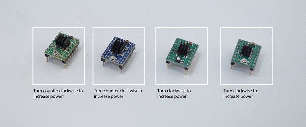
Note that you want to turn the current down if the driver is shutting down due to heat. Refer to this to know which direction to turn. It shows the direction for increasing so you want to do the opposite like a 1/16th of a turn and then test.
-
Also check that the heatsink is attached and that the driver and heatsink are getting airflow from the fan.
-
Just so you know, the step files for the at least the bottom lasercut part doesn't seem up to date.
Does anyone know where to get the latest step files?
-
As a poor speller myself (native English speaker so I have no excuse), it's unfortunate that misspellings in a presentation give the impression of lack of knowledge, intelligence and/or education when that impression can be quite incorrect. In my case, the US education system wasn't the best when I was in school. It's better now but no where near other countries.
Anyhow, that dragnet feeder is pretty slick. I was thinking of doing something similar where both the idler bearing and knurled bolt are driven but I couldn't workout the geometry that would allow it to be powered by one source while maintaining the ability to adjust it. Seems like you have...
One thing I did I really liked was to replace my UM1's feeder gear set with a herringbone set. It allows very little backlash. If you have backlash, you might considered a similar solution.
-
Good presentation. However, you need to spellcheck!
-
Someone wanted to do a layer-by-layer timelapse using a similar command. Someone else suggested the m42 command in the layer comment.
You can probably leverage the same solution for your use. However, it requires you to tap into the board expansion points and I think you will need to solder a header on to do so.
https://groups.google.com/forum/#!msg/ultimaker/vZok0JVD430/jVH5kOwj620J
Daid
4/12/12
Actually, you don't need to touch Arduino code. You can change pins with the M42 code. Combine this with G4 (delay) and you can code your camera trigger in pure GCode.
For example:
M42 P23 S255 ; Set the trigger camera pin high
G4 P100 ; Wait 100ms
M42 P23 S0 ; Set the trigger camera pin low
Gijs
Nice!
do you also know how that corresponds to the 1.5.4 ultimaker pcb? because from the wiki it's not clear to me where I would connect the opto-coupler,
cheers,
Daid
The pin numbers correspond to the numbers shown here:
http://www.reprap.org/wiki/Ultimaker%27s_v1.5.4_PCB#Pinout_of_Extension_connectors
I recommend you use one of the PWM or ANALOGUE pins, because the EXP1 and EXP2 are used by the Ultipanel later on, if you get one.
(The analogue pins can also be used as digital outputs, something you might not guess from the name)
Gijs
OK, suppose I would use PWM 8 and 9, what would then be the corresponding M42 pin assignment? just P8 and P9?
Daid
Yes, P8 and P9 would do the trick then. Small note about the PWM outputs, those can be PWM driven, not sure if the Arduino will do that or not, just be sure to use S0 and S255, no values in between to enable/disable the output.
-
Ooooo. A unicorn and a black magic feature... nice!
-
Sorry, I do not know about an Android version. I have a Windows Phone (yes, I'm one of seven people in the entire world) so I have no hope for me!
-
I don't have an ipad but the UI really looks good for kids.
http://makezine.com/2014/05/14/making-toys-with-modio-at-makercon/
-
No problem Daid. I wasn't complaining. Betas have bugs. I was just giving you more information in case you were still trying to determine why it wasn't working.
With the latest firmware built from the latest source, the beta Cura and the changes mentioned by Dim3nsioneer, the volumetric stuff seems to work.
However, I've yet to print a part with a lot of retracts so we will see how that goes.
-
Odd, as there are zero changes in that part.
Daid,
I don't know if this helps but....
The "Install default firmware,,," menu item just opens a progress dialog that just sits are "Reading firmware...."
However, "Install custom firmware" works fine.
I chose Ultimaker with custom heated bed and I wonder if that trips up the "default" firmware upload. Is there even a valid "default" firmware for the UM1 + custom bed solution?
-
Ahhh that is probably the part I'm missing. My attempts to use the volumetric stuff has the material feeding like crazy!!! So hopefully that is address with the M200.
Thank you.
-
I tried the raft but couldn't separate the print from the raft. Any suggestions? UM1 at the defaults but with a heated bed. Temps were 220/70. Trying a second time @ 220/50.
Second attempt had the same problem. The raft and the part are basically one can can't be separated.
This is a UM1 using ProtoParadigm's red PLA.
-
Is it uncommenting this in the configuration_adv.h?
// #define FWRETRACT //ONLY PARTIALLY TESTED
And then start by copying the retract settings and using the controller to set or using M207 and M208 ?
-
I'm just doing my very first print with the new volumetric RepRap flavour on my UM1.
Can you describe what needs to be done to support the volumetric mode of the firmware?
I simply switched to it and well it didn't go well!!!
Thanks.
-
I used the PID autotune to set up Jason's heated bed. The temperature locks on the set point quite well.
-
The problem with linear regulation is that when not at 100% or 0%, the regulating part must dissipate a lot of power which is usually in the form of heat. For example, I have a bed that is 10 amps @ 24v which is 240W (power = voltage * current or P=VI). If that where linearly regulated at 50%, the bed would get 120W and the regulating part would have to do something with the other 120W.
Have you ever unscrewed a 120W blub that was on? Very hot...
So often the regulation is done in full on or full off model switching quickly enough that something (in this case the bed) is averaging the on and off times and smoothing the change. So if a MOSFET turns the bed on for 1/10th of a second and then turns it of for a 1/10th of a second, the on/off time is happening 5 times a second. Because the temperature of the bed can't change immediately when heating or cooling, the average power consumed is the ratio of on time to off time or in this example 50%. From the MOSFETs perspective, it is either on so the voltage across it is 0 or off so the current through it is 0. If you look at the P=VI formula, if V is zero or I is zero, the power consumed or dissipated is 0.
Well, the caveat is that the MOSFET is perfect and in the real world, nothing is perfect. The MOSFET takes a small amount of time to transition from off to on and on to off. During this time, it is sort of in a linear mode and so dissipating power as heat. However, again like the bed, the MOSFETs temperature can't change instantaneously so it's temperature is based on the time it spends between full on or off to the time it is full on or off. This ratio is very small.
The SSR I'm using has a turn on of 1ms and a turn off time of .5 ms. So as long as the switching frequency is low so that the SSR spends more time on or off than in the middle, it won't need to deal with much heat.
Then there is also the fact that real SSRs, unlike the theoretical model of a switch, have a small amount of resistance. P as equals I squared times R. But MOSFETs tend to have a very low value of R keeping the power they need to dissipate low too.
Welcome to electronics 101 ;-)
-
Yes, no secret but it does say closed in the link so I didn't feel comfortable sharing it. However, you are better situated to know if it can be shared.
-
PID seems to be more accurate or at least more granular so that the temperature is more closely controlled to the set point and doesn't overshoot after settling in. I believe it also regulates better when the conditions change such as when the fan comes on.
For the bed, I believe that earlier in the thread there was a discussion that regulating the temperature extremely close to the set point isn't required and that bangbang is more than sufficient.
I went with the SSR just because I like solid state and dislike clicking....
With both that SSR and SSRs and MOSFETs in general, you need to be aware of the turn on/off time. That SSR has a 1ms second turn on (or was it off? well whatever it was the opposite was quicker at .5ms) so the PID on/off sequence can't be faster than 100hz. Just looking at the LED, the PID looks like it is switching at 5-20hz or so so no problem there.
In either case, the current is only on or off. Neither mechanical nor SS regulates the temperature linearly such as with say 65% current. It's always PWM.
-
They were sliced with Cura 14.04-RC1. I did notice that there is a significant seam on the inside but they were solid so Cura may have did something such that it didn't attempt to create an internal finished surface.
Looks like you can get older versions here : http://software.ultimaker.com/?show=all
The betas are closed but you can get them if you know were to look on the forums.
-
20x20 cylinders printed on a UM1 generated out of DesignSpark Mechanical.....
One has twice the number of faces as the other but I can't tell which. I think I'm at the limit of the UM1's resolution.
Cura 14.04-RC1
Layer 0.1mm
Shell 0.8
Bottom/Top .6
Fill: 0
Speed 50
-
I went the expensive way http://www.phidgets.com/products.php?category=9&product_id=3950_0
works well in PID mode and optically isolated. doesnt even get warm
-
Hmmmm my post got lost or I never submitted it... Anyway the marlin firmware builder exposes the advanced option but the site notes that it is something that:
"does some fancy pressure calculated extrusion amount which never works as far as I know"
See the ? next to the Enable extruder advance:
http://marlinbuilder.robotfuzz.com/
-
Your link got a little mangled : http://www.3dizingof.com/3D-Printing/product/cells-bowl-by-dizingof/
I don't know how hard generating those models is. If it is truly something that can be described mathematically, look at OpenSCAD which uses a mathematically language to generate a model.
These, while not as organic as your link were generated with OpenSCAD:
http://www.thingiverse.com/thing:99020
Complete heated bed kit for Ultimaker
in Third party products & modifications
Posted
PID is implemented by varying the pulse width time (PWM). So PID and PWM are related. Bangbang is a slow on and off cycle and is determined by the temperature falling below the desired temp by a certain amount causing the relay to switch on until it is above the set point by a certain amount. That on and off might take several seconds. PWM switches on and off many times a second trying to supply just enough power so that the temperature is kept very close to the desired temp.