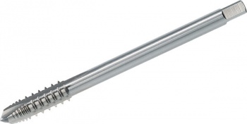
I tried tapping too with straight taps (I had never seen those spiraling ones, didn't know they existed), but indeed it didn't work well. Even not when tapping manually and reversing very often: 1/4 turn forward, 1/8 turn backwards. Chips would get stuck and the plastic would melt (even at very low speed, lots of cooling time and lubrication). Also, threads were very weak and got worn-out very soon (M3, M4, M5).
So for most of my models, I now use standard nylon M4-screws instead, with a caged nylon nut that can not fall out. This goes a lot faster, and it works better: the thread (nylon nut) is much stronger than a 3D-printed and tapped one, and it can be replaced if required.
Mostly variations on these concepts:
1. Fully caged nut; the backside of this opening is closed, it is only open on top. If the opening is tight enough, the nut will even be clamped. If slightly wider, it will wiggle, but not fall out (unless you totally remove the screw and hold it upside-down).
2. Another variation on the same concept:
3. Recessed hex opening for keeping the nut. This is a test model to try-out required tolerances for an M4 nut (ca. 7mm diameter between flats).
4. I haven't tried this yet, but someone (I forgot the name) suggested using "metrinch" cages for clamping the nuts. They seem to wear-out less than traditional hex holes, and allow tighter tolerances, since problems with 3D-printing are mostly around corners.


Recommended Posts
AndersK 59
Are you using straight taps in blind holes?
Try spiral taps instead then. They are designed to pull the chips upwards instead of pushing like the straight taps.
Link to post
Share on other sites
RudydG 62
I use straight taps yes. Almost never blind holes, but the evacuation of the debris is the main problem. Maybe i can try these.
Thanks.
Link to post
Share on other sites