


personal-drones
-
Posts
257 -
Joined
-
Last visited
Content Type
Forums
Events
3D Prints
Posts posted by personal-drones
-
-
Yesterday I was printing a box for my nozzles.
After a while, I had a look at how it was coming out, and this is what I saw:

Pillowing. I hear Illuminarti's voice from somewhere above me. "It's the fans", he says, "It's the fans".
I look at the fans and indeed they are not spinning. Check the led display, it says fans 100%.
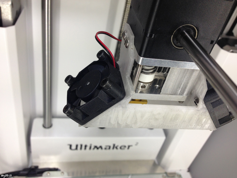
So I stop the print and start playing with the wires coming out of the head. And indeed, if I tilt the cables in a certain way, fans will start.
I expose the cables, but visual inspection does not help, everything looks fine. Indeed, there is one connector that must be defective, as when I play with it, power will come and go to the fans. Nothing wrong to be seen though.
This is what I have, the defective spot is the connector with two green wires attached at the top, the one to the right of the image below.

I decide for a radical solution. I cut off all the connectors part:

Then take out the soldering iron

Rewire everything without connectors. Who needs connectors after all


The fans are in series.
The yellow cable is positive, the green cable is ground.
The yellow cable must be soldered to one of the red wires from one of the fans (fan 1).
The green cable must be soldered to the black wire on the OTHER fan (fan2).
Then you can connect the black wire from fan 1 to the red wire of fan 2, to close the circuit.
I did not connect any wires directly, but used some short pieces of spare wire as bridges, to leave some room for future rewiring and to avoid having cables too short or too tight.
I thought I would share this just in case someone has the same problem. Works perfectly now. The whole thing took maybe 30 minutes, good to be on the road again
-
If you install the previous version of the firmware, will the printer behave or do you still have problems. I wonder if you may have some loose connections to the board, and this would be a way to test it, so that you are really sure you can blame it on the firmware.
-
Hi Warderoid, the object as it is won't fit my UM2 build plate in cura, some scaling down is needed for the model to "become blue" in Cura.
My suggestion, if you regularly have to print such large pieces, is to get the Olson Block and use a 0.6-0.8 nozzle. This will let you print much faster, at an higher layer height, without fear of underextrusion.
Otherwise you could try layer height 0.2, speed 40 for inner shell/outer shell/infill and see if your times get better. Then print at 220°C.
The problem is that you have some quite steep overhangs in the upper part of the model. Raising the temp or speed too much will not help quality.
However for such big pieces with relatively low details, a bigger nozzle is the real solution as it lets you keep the temp down while still achieving good speeds and layer height.
For the Olson Block see this thread:
and this website to buy: http://www.3dsolex.com
-
Are you sure you are really printing at 25? Did you set 25 in the advanced tab of cura, or did you just set 25 in the basic settings speed (which will do nothing). Those overhangs in the lower part of the body are really nasty and they don't look printed at a speed of 25.
-
Bonjour Huru,
Speed il faut faire attention a aller dans le tab "Advanced" de Cura et régler la vitesse pour les differentes parties de l'impression.
Tu va voir que le default pour l'infill c'est 80, ce qui ne va pas du tout.
Mon conseil c'est de laisser tout comme c'est deja, sauf:
inner shell: 40
infill speed: 40
outer shell: 30
Temperature 210
Pleateau 55
Dans le tab "Basic":
Layer height 0.1
bottom/top layer: 0.8 (et non pas 0.6, le default)
print speed 40
(en principe le speed dans le Basic c'est ignoré, ca va utilizer les speed que tu decide dans le tab Advaced)
-
Izzy beautiful job, solves an important problem for the placement of the UM2. Indeed the fact that you have to access the back easily is kind of limiting on where you can place the machine and this is a nice solution. Will look into the thing, thank you!
-
Alors la ca va beaucoup mieux
Oui celles ci tu les peut imprimer, en principe tout ce que tu trouve sur myminifactory est bien imprimable.Pas pratique parce que un layer de 0.02 mm c'est tres "fragile", c'est plus facile qu'il se "dechire", c'est plus difficile a gerer en general, ca prend un temp "impossible". Par example pour les portes a faux en general un layer plus epais peut donner des resultat meilleur que un layer ultra fin. Si tu insiste avec 0.02 mm tu va galérer, ce n'est pas le bon choix pour avoir un qualité excellente avec Ultimaker. Par contre 0.06 mm est tout a fait faisable et ca donne des bon resultats. Mais encore, pour certains modeles 0.1 mm va etre mieux de 0.06 mm. En somme, la qualité est donnée seulement en partie de l'epaisseur des layers. Il y a d'autres facteurs, comme la vitesse, le choix du materiel, les supports utilisés (les supports sont imprimés avec la piece), le traitement post-imprimage etc...
3 400€ :shock:
0.06 cm tu veux dire ? Et c'est quoi "pas pratique" ? Et tu entends quoi par support ? Je sais jamais si ce sont des supports imprimés en plus ou qu'on ajoute manuellement. Si c'est la seule alternative pour des objets imprimés, je me contenterai de figurines assez simples... Puis bon, je passe mes journées au lycée donc je suis pas pressé je peux pousser la précision au max :cool:
Par exemple, pour me donner une idée en attendant les vacances pour aller à Mulhouse dans un Fablab, est-ce que tu penses que cecihttps://www.myminifactory.com/fr/object/the-beholder-5477 est imprimable (sans compter le temps, les supports, juste la qualité d'impression qu'il est possible d'atteindre) ?
-
Certaines des figurines dans la page ne sont pas du tout evidentes/faciles a imprimer. Ca va demander des supports e une bonne dose de travail post-impression pour chaque figurine. Et tu pourrait trouver certaines figurines pratiquement impossibles a imprimer comme il faut.
20 microns ce n'est pas pratique et pas necessairement ca va te donner une meilleure qualité. Tipiquement tu va arriver maximum a 0.06. 20 microns en pratique ca ne s'utilise pas.
La precision depend surement de la vitesse d'impression, plus lent c'est mieux.
Pour faire des choses très petites et très précises, une Form1+ pourrait etre un choix meilleur d'une Ultimaker.
-
Izzy very smart, very nice, thanks for sharing the photos! When I enlarge it says I do not have permission to see the photos, any setting to make them "public"?
-
C'e una interessante discussione in corso qui sullo sviluppo di un blocco riscaldante alternativo per la UM2 che consente di sostituire gli ugelli, chiamato "Olson Block" (dal nome del membro del forum Anders Olson che lo ha sviluppato).
Io l'ho installato e sono molto contento di averlo fatto:
Ora posso usare ugelli da 0.25, 0.6, 0.8 in alternativa a quelli standard da 0.4.
Posso dedicare (l'ho già fatto!) un ugello ai materiali abrasivi come bronzefill e XT CF20.
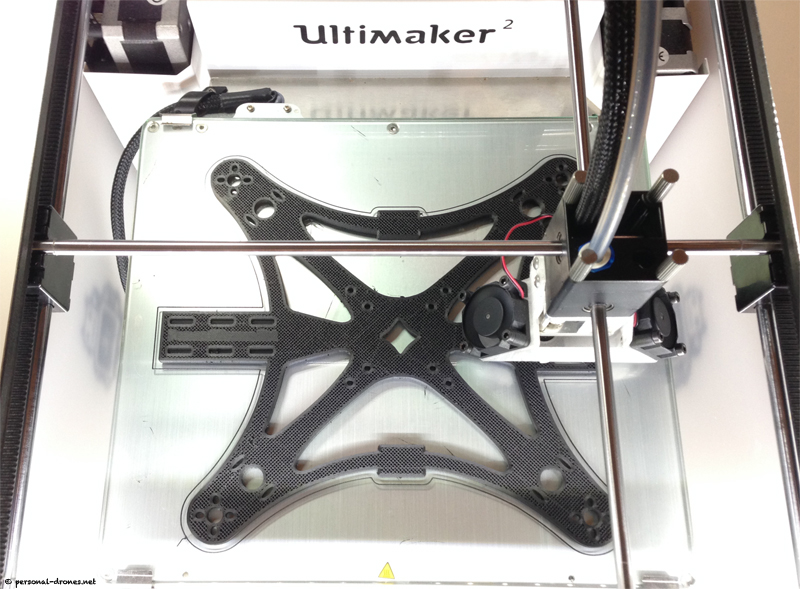
Il sistema dispone di una serie di accessori collaterali. In particolare è raccomandato l'utilizzo di un telaio per le ventole dedicato, da stampare (vedi foto sopra, leggermente modificato rispetto all'originale), scaricabile qui. Si può lasciare il supporto ventole originale in alluminio ma sono necessarie alcune accortezze nel montaggio dell'Olson Block. Poi è possibile installare il cosiddetto IK2 Solex Insulator, che è un anellino che protegge il teflon coupler dal calore prolungandone notevolmente la durata di vita (efficacissimo) ed è possibile comprare una serie di ugelli di varie dimensioni.
Il tutto è ora disponibile sul sito
gestito dal membro del forum Swordriff.
Raccomanderei a chiunque di effettuare questo upgrade, aggiunge veramente una dimensione in più alla UM2. Sono a disposizione per qualsiasi domanda.
-
Amedee comme premier essai j'ai decidé de faire 4 mm. Le Ecks original, en fibre de carbone, c'est 3 mm. Infill 30%, shell 1.2, bottom-top 1mm, layer 0.1 mm. Ces truc la ca tombe du ciel, ca doit etre resistant (et un peu flexible au meme temps)
-
J'ai presque terminé d'imprimer mon dessin de quadcopter inspiré du modele Ecks Fibre. C'est un peu moins sexy des post précedents, mais j'espere que ca pourrait interesser tout de meme
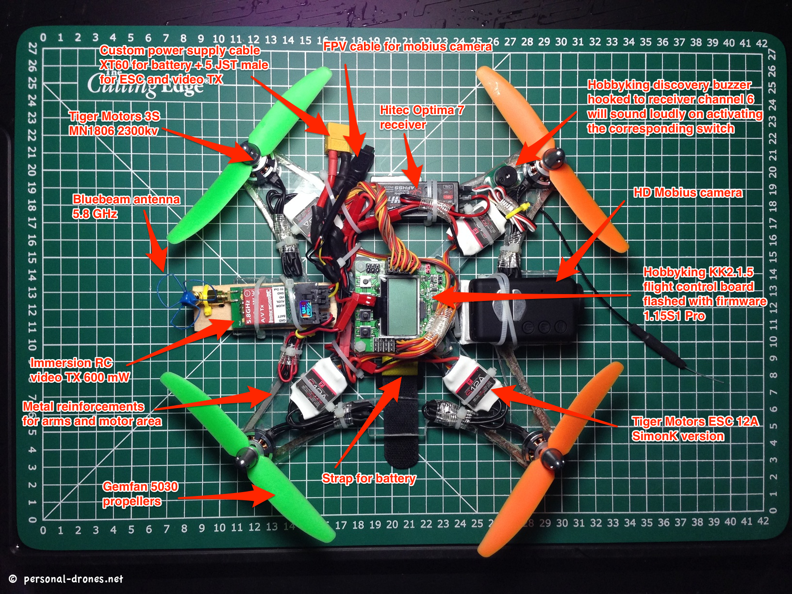
Par rapport a la forme originelle du Ecks j'ai ajouté deux petites plateformes pour la camera (sur le devant) et l'emetteur video (derriere). J'ai aussi ajouté deux petites plateformes latérales. In n'y a jamais assez d'espace pour le composants sur ces petits quads.Dans la foto en bas vous pouvez voir le meme modele, monté, que j'avait decoupé manuellement en plexiglas - voir
Pas particulierement robuste, je suis sur que la nouvelle version, en Colorfabb XT CF20 va etre bien plus resistante. Et bien sur, cette nouvelle version va etre disponible pour etre telechargée et imprimée par tous! Merveilles du 3D printing!
-
Printing a quadcoper frame I designed based on the Ecks Fibre model. With respect to the original design I added two little platforms for the video camera and video transmitter at the front and back.
I had already built one from plexiglas, cut "by hand" with a dremel (see the second photo). Amazing now to be able to design it, print it and possibly share it thanks to my UM2.
Colorfabb XT CF20, most appropriate for a quadcopter in general and for the Ecks Fibre in particular
If you are curious about how to make one of these things, you will find a full description of this build here: http://www.personal-drones.net/plexiglas-mini-fpv-quadcopter-experimental-build-based-on-the-ecksfibre-design/.
-
This is a smart and simple idea, like it a lot
-
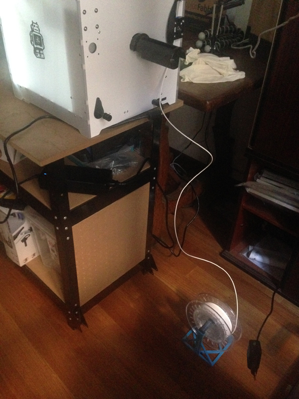
I would recomend making yourself a lazy Susan base, that way if you want access to the rear of the machine to access the filament feeder etc. you can just spin it round.
I used a 300mm lazy Susan bearing, and a good 18mm thick wooden shelf from a DIY store, along with some rubber feet. cutting one long length of board for the base mount the bearing on it then the top board for the printer to rest on. My bottom board is long enough to rest against the wall and that the top board can rotate without hitting the wall. I have also cut a large hole through both boards at the bearing centre so that the leads (power and USB) can be feed through and out.
This little accessory gives me very easy access to all side of my machine very quickly, for Filament changes.
Izzy very interesting. Any chance you can post a picture of your setup?
Benjamin I suggest you buy a couple of replacement teflon couplers, so that when it's time to change it (after 3-400 hours of printing), you won't have to wait 2-3 weeks for delivery.
-
Very nice print! I had the same problem with tiny rounded structures going up, nearly impossible to keep them really in place. Going slower can help but it is not a "final" solution. It was heroic that you standed there and acted as a "human support"
I would guess you could activate Cura supports, play with the settings in the expert settings and see if you can add some more useful support structures. If you have simplify 3D you could manually add some additional supports. I hear that also meshmixer allows you to add supports, not sure how though, still have to try that.
-
As Tommy said. Try to print with a Brim so that the piece stays in place.
Hi,
This is my first post with Ultimaker.
I am fairly new to the 3d printing world. In Janurary this year I got my Ultimaker 2. I have printed quite a few things over the past few months, learning as I go.
But I am having a huge problem with one part that I am trying to print. I have failed at least 6 times. And I need some advice.
The file I am trying to print is this:
https://www.dropbox.com/s/zsn96gard590bvq/skirt.stl?dl=0
And everytime I try to print, I get this:
https://www.dropbox.com/s/jk7f4eca2u3c308/2015-03-19%2008.48.20.jpg?dl=0
I am using mostly default settings, except the layer height is 0.06mm, and speed is 30mm/s.
If I print without supports, I get that result everytime.
If I add supports, it fails even quicker.
I have also tried glue from the glue stick, as well as hairspray, same issue.
Any suggestions?
-
FormFutura c'est bien aussi, j'ai eu des excellent resultats et pas de problemes.
-
The I2Ks are delayed because it is difficult to source the right material.
I have decided to ship everything else, and send the I2K later, looks like 1-2 weeks.
Got my I2K from the previous batch yesterday, thank you Swordriff. Installed it together with a brand new teflon coupler, everything looking perfect so far. Will check my teflon coupler in 200 hours of print or so to see if I get the expected protection from deformation. If it really works as advertised (I am sure about that), this will be a little game changer in itself, while waiting for the Impossibilium thing.
-
As tu essayé de calibrer le plateau? As tu la meme chose avec un modele different, n'importe quel modele, pour un test?
-
Ciao non è che caricheresti una bella foto del tuo setup?
Salve a tutti, io ho un' opinione completamente diversa. Secondo me il feeder originale non è il colpevole, anzi se "mangia il filo" vuol dire che la forza è più che sufficiente. Io ho smesso di avere inceppamenti sistemando il supporto bobina. Sostanzialmente quando il feeder traina il filo produce delle accelerazioni e se la bobina non è "frizionata" cede più filo del necessario. Non mantenendo la giusta tensione alcune spire della bobina tendono ad accavallarsi ed una volta verificatasi questa condizione la bobina si blocca e non riuscirete a farla avanzare anche tirando a due mani (chiedere ai pescatori queste cose le sanno).
Se avete una spugna PIATTA tipo quelle delle confezioni delle schede grafiche dello spessore di 2/3cm, attorcigliatela e mettetela all'interno del cannotto di supporto della bobina. Deve fuoriuscire leggermente dall'albero tipo 3/4mm. Questo crea una zona di frizione tra bobina e albero sufficiente a mantenere in tensione il filo ma non troppo da creare sforzi al motore. Fate però attenzione a non far svolgere la bobina quando la manipolate oppure quando cambiate il materiale sulla stampante. Se mantenete le spire ben avvolte come quando la bobina è nuova tutto fila liscio. Se capitasse, però, con un pò di pazienza riavvolgetela correttamente. Costo dell'intervento circa 5', se avete la spugna a portata di mano. Ciao
Io mi sono organizzato così:
Nessun problema di attorcigliamento mai.
Per i problemi del filamento mangiato, nella mia esperienza dipendono sempre da una resistenza al passaggio nell'hot end. Spesso dovuta al famigerato "Teflon coupler", quel pezzetto bianco di teflon in cui si inserisce il tubo bowden lato hot end. Va sostituito circa ogni 300 ore di stampa o meno. Con il tempo si deforma e inizia ad opporre resistenza al passaggio del filamento, che non potendo avanzare viene mangiato dal feeder. Il mangiamento a sua volta fa si che a un certo punto il feeder perde la presa, e poi tutto si blocca.
-
Netfabb basic has a very nice ruler tool to measure distances in stl files. You could measure the hole in netfabb so that you can calculate precisely how much you have to scale the model in Cura,
-
Oppure scrivete un thread in inglese in questo forum, vi consiglio la sezione Modifications and Hacks.
Questa è un'ottima idea. Aggiungerei di provare a contattare direttamente Ultimaker (ad esempio SandervG sul forum), è possibile che si interessino e possano dare qualche buona idea (è anche possibile che vi ignorino ovviamente).
-
Le XT , je viens de l'acheter mais pour l'instant je n'ai pas encore trouvé les bons réglages et les résultats sont assez décevants
Pour le XT je te conseille outer layer speed 20, inner layer speed 30, infill speed 30, temperature 240, bed temp 70, layer 0.1

rough surfaces (picture heavy)
in UltiMaker 3D printers
Posted
My suggestion is to do a deep cleanup of the nozzle with the atomic method, take a deep breath and start over.
If you print PLA over 230, the results will be ugly, like we can see in your pictures. PLA is supposed to be printed at 210°C on average. You can get up to 230 max, but the results will be nicer at lower temperature.
In order to keep the temperature in the correct ranges, and avoid underextrusion, you need to print relatively slow.
I suggest you start from the quick print, normal quality. Then go to expert settings and click yes when it asks if you want to keep the settings. Then, leave everything as it is in basic settings, except bottom/top thickness that is better set to 0.8.
Then go in expert settings. Again leave everything as it is except: infill speed and inner shell: 40, outer shell: 30.
Print at 210°C. Bed temp: 55°C
This is it. If you follow this very closely and your nozzle is well cleaned with the atomic method, you should have some nice PLA prints.
Remember that every time you change material, and even possibly every time you change spool, consider doing a couple of atomic pulls to cleanup the nozzle.
Your teflon coupler 100% needed replacement.
XT and woodfill are much more difficult to print than PLA, each for different reasons. In my experience XT needs to be printed much slower that PLA (about half the speed) and at 245°C, while woodfill is a totally different story. My suggestion is to stick with PLA until you master it, and then try the other materials.