Jump to content

Damage assessment after failed hotbed upgrade


Recommended Posts

Posted · Damage assessment after failed hotbed upgrade

Hello everyone!

I am dearly seeking help after a failed hotbed upgrade:


The upgrade entailed a custom aluminium bed, MK2 pcb, external pollin PSU (Computer-Schaltnetzteil FSP FSP4 6094-351112), epcos 100k thermistor and the 4,7k resistor at R4.


First I checked my connection according to the wiki: (http://wiki.ultimaker.com/Heated_Bed...)

"

Secondary DC supply, e.g. 12V for reprap pcbs:


The ground of this supply should be connected to the ground of the Ultimaker supply. Than one power connection of the PCB goes to the +12V of the secondary supply, while the other goes to the pin2 of the HotBed connector of the Ultimaker PCB. Its a lowside n-channel Mosfet circuit, thats why this should work. (I have not tried this personally, please be careful). Then the Ultimaker PCB should be able to control the bed.

"


This meant connecting MK2- to PIN2, MK2+ to PSU +12V, PSU- to PIN1 (the eagle board shows PIN1 is connected to ultimaker shield ground).


I powered up the external PSU about a second before pluging in the ultimaker PSU cable (sidenote: my ultimaker power switch worked for ~ 1 week...since then I've been pluging in and unpluging the ultimaker psu cable to turn on/switch off the printer)


Immediately I smelled smoke and the lights from the Ultipanel LCD and blue LED strip went out, leaving only the eerie green glow from the MK2 board LED. This surprised me especially because the blue led strip is connected/powered directly at the ultimaker shield power jack!


Anyway..it's really a great shame... I have had extremely reliable and satisfying print results after a recent extruder upgrade...


I welcome any explanations and hints on damage assessment or repair!


regards,


Michael Wakileh

ultimaker shield

extruder upgrade

print


  • Link to post
    Share on other sites

    Posted · Damage assessment after failed hotbed upgrade

    That sounds like it should have been okay. I would have plugged in the UM first, but I can't think why that would be a problem. My head is sleepy - I'll read this again in the morning.

    Are you sure you didn't hook up the 12v supply backwards?


  • Link to post
    Share on other sites

    Posted · Damage assessment after failed hotbed upgrade

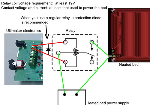
    it looks like you have tried to pull the power from the Ultimaker board rather than use the heatbed output to drive a relay? i couldnt open the wiring drawing to check so I'm just going off the picture. I've said this before but I'm going to say it again, yes it is nice to be able to run a hotbed from the Ultimaker board but there is a lot that can go wrong with expensive results. There is a kit on ebay which includes everything you need to run a stand alone system and its half the price of a replacement Ultimaker main board. You may be able to repair what you have but once you have replaced the components that have obvious damage, you will probably find others and may take some time.

    Paul


  • Link to post
    Share on other sites

    Posted · Damage assessment after failed hotbed upgrade

    Hi! Ok so today I got back to the issue of the lights... the blue LED strip turning off got me thinking the official ultimaker psu might have tripped...

    as the green MK2 led was still turned on when the LCD and LED strip turned off the external psu must still have been powering the hotbed?

    so I measured the Ultimaker PSU Voltage: 0 Volts... after unplugging it from the mains for at least 10 seconds I got the 19 Volts back.. plugged that back into to Ultimaker shield and it appears to be working!!! (autohoming and temperature controll of the hotend functional...)

    So I got curious about where the smoke came from and replicated the issue =D (for about 0.5 seconds) ..the smoke comes from the Hotbed FET solder joints, the Ultimaker PSU trips, I disconnect the eternal hotbed PSU... then revive the machine by unplugging the Ultimaker PSU from mains for at least 10 seconds...before pluging back in... (and yes autohome and pid hotend control still work... testprint to follow)....

    any ideas on whats going on here?

    Could the problem lie in a faulty solder joint? (I've had issues with this when I first got the machine)...

    regards,

    Michael


  • Link to post
    Share on other sites

    Posted · Damage assessment after failed hotbed upgrade

    You should measure the current going to the HPB.


  • Link to post
    Share on other sites

    Posted · Damage assessment after failed hotbed upgrade

    I can only calculate it as my meter is rated 10A max.. and i will likely look for an opto isolated solution.. i assume the control signal is ttl? regards

  • Link to post
    Share on other sites

    Posted · Damage assessment after failed hotbed upgrade

    it could be a faulty solder joint at the hotbed mosfet, if it is the hotbed mosfet could be in a state between conducting and isolating with a few ohms, this could quickly kill your mosfet.

    to exclude this:

    (without any hotbed stuff connected)

    take a voltmeter or a scope an measure the right pin(when seeing the mosfet from behind) vs ground. it should be on ground level. now tell your machine to heat the bed, the pin should now be above (dont know exactly) ground level, at least 5 volts.

    could also be possible you connected your hotbed psu in reverse, what would cause your hotbed mosfet to act like a diode shortening the hotbed psu.


  • Link to post
    Share on other sites

    Posted · Damage assessment after failed hotbed upgrade

    Your wiring sounds all wrong. Hopefully there's no permanent damage to the UM board because they're not cheap. Your computer PSU should be connected to the switched side of a relay going to the heated bed, while the leads from the heated bed outputs on the UM board should go to the switching side of the relay.

    While the traces in the UM PCB beneath the heated bed connectors could probably handle 10A (assuming it's a 2oz board), the rest of the board is not setup to handle switching that sort of current.

    Read the heated bed wiki again, it's pretty clear.

    http://wiki.ultimaker.com/Heated_Bed

    9190518741_53e550ddcc.jpg


  • Link to post
    Share on other sites

    Posted · Damage assessment after failed hotbed upgrade

    UM electronics is redesigned cheap Arduino board (with cheap ATMega 2560) with shield for motors... It isn't expensive, it is just well overpriced like everything in Ultimaker... (well I don't blame them, if I could have 300-400% margin on my products and people still would buy it, why not ;))... Nothing fancy, nothing expensive, just well overpriced.

    You need to use relay which will be controlled by UM and relay will "control" heated bed PSU...

    You can't connect PSU directly to UM... (same like you would like to connect directly motors to ATMega 2560 so it would control it directly ;), you may connect for example some low current receivers but nothing else)...


  • Link to post
    Share on other sites

    Create an account or sign in to comment

    You need to be a member in order to leave a comment

    Create an account

    Sign up for a new account in our community. It's easy!

    Register a new account

    Sign in

    Already have an account? Sign in here.

    Sign In Now
    • Our picks

      • UltiMaker Cura 5.7 stable released
        Cura 5.7 is here and it brings a handy new workflow improvement when using Thingiverse and Cura together, as well as additional capabilities for Method series printers, and a powerful way of sharing print settings using new printer-agnostic project files! Read on to find out about all of these improvements and more. 
         
          • Like
        • 18 replies
      • S-Line Firmware 8.3.0 was released Nov. 20th on the "Latest" firmware branch.
        (Sorry, was out of office when this released)

        This update is for...
        All UltiMaker S series  
        New features
         
        Temperature status. During print preparation, the temperatures of the print cores and build plate will be shown on the display. This gives a better indication of the progress and remaining wait time. Save log files in paused state. It is now possible to save the printer's log files to USB if the currently active print job is paused. Previously, the Dump logs to USB option was only enabled if the printer was in idle state. Confirm print removal via Digital Factory. If the printer is connected to the Digital Factory, it is now possible to confirm the removal of a previous print job via the Digital Factory interface. This is useful in situations where the build plate is clear, but the operator forgot to select Confirm removal on the printer’s display. Visit this page for more information about this feature.
          • Like
        • 0 replies
    ×
    ×
    • Create New...