Jump to content

Pleas CREATE This for ME


mnis

Recommended Posts

Posted · Pleas CREATE This for ME

Hello

Currently, I am seeking some help. I'm looking for someone who can create me two engine covers for the UM2 as a 3D object new.

I would like to print these covers in semi-transparent blue. And i Need this 2 parts for further experiments.

Both engine covers are identical, only the air inlets must be adapted for each site. The overall material thickness should be at least 3mm. The lower front area should have a rectangular air inlet opening. Just 15mm above the interior machine-floor. Inside the covers an angled air duct should allow the mounting of a 40mm fan (5mm holes) right dare, nothing more.

Perhaps you know someone who would do it for me. I do not want to wait until I've learned it myself.

Thank you for your attention and have a good time.

Markus

  • Link to post
    Share on other sites

    Posted · Pleas CREATE This for ME

    Just some comments.

    You have to print the Covers in 2 Parts and screw them together since the total length is 23.5cm.

    The fan inlet would not need to be modified. just mirror the part in Cura.

    the hard part will be nut used on the side to screw the cover against the sidewall of the ultimaker. What nut do you want to use?

    Why 3mm? there is no physical stress on that stuff. 1.2mm should be plenty.


  • Link to post
    Share on other sites

    Posted · Pleas CREATE This for ME

    Does that mean you would want to make it for me? :shock:

    Furthermore , I would be very happy. :-P

    Have I described it good enough? :oops:

    Among the covers :

    Two piece is not so good, I thought the covers would fit diagonally on the platform. But I have not measured it. Alternatively, it would not be so bad if the covers are slightly shorter, close to the limits. Also conceivable, a long piece and a short piece above for gluing or stuck.

    There must be no screw-thread, nowhere. I'll probably use some kind of bolt / pin, because I 'll think of something. Simply use a 3mm hole. Also possible a pit for an M3 nut.

    I would like to use a thicker wall, so that various fillings, such as Honeycomb pattern, can be tried.

    About possible temperature problems I 've thought, but it is probably not critical, since I will be using this machine print no ABS. Thus, the bed temperature is located only in the first layers at 60 degrees, and during the printing time somewhere between 40-45 degrees.


    Many thanks for the time invested. I can give you a small donation also very happy.

    Markus

  • Link to post
    Share on other sites

    Posted · Pleas CREATE This for ME

    I didn't quite understand the part about the air inlet and fan mount so I just put something there for now. Is this remotely close to what you were thinking?

    cover


    (with a duct connecting the air hole and the fan mount)


  • Link to post
    Share on other sites

    Posted · Pleas CREATE This for ME

    Does that mean you would want to make it for me? :shock:

    Furthermore , I would be very happy. :-P

    Have I described it good enough? :oops:


    You described it well enough so i know exactly what you want..... only problem though..... time..... and a damn long project list..... and this would not get an important flag.....

    btw i thought also about the temp problem..... thats also why i would use a small wall. and a 60mm fan atleast :D


    I didn't quite understand the part about the air inlet and fan mount so I just put something there for now. Is this remotely close to what you were thinking?


    yes :D

    but now please in printable without support :D

    you could always contact me over skype if you want. contact details are in my profile :D


  • Link to post
    Share on other sites

    Posted · Pleas CREATE This for ME

    Honestly, I have not expected that someone has time for my little concern.

    Thank you both.

    @ IRobertI

    That hits almost exactly.

    The air intake should be no more than 15x40mm, which should suffice. From the air inlet to the fan mounting plate, a closed channel should be.

    You can also gladly place a / your logo on it, and or your creative thoughts on the walls, I accept almost anything... :mrgreen:

    I am now quite happy ...

    Markus


  • Link to post
    Share on other sites

    Posted · Pleas CREATE This for ME

    yes :D

    but now please in printable without support :D

    you could always contact me over skype if you want. contact details are in my profile :D


    No support needed if printed flat on the bed.

    @mnis: I need exact measurements for the fan (main hole diameter and position of screw holes), I just guessed a bit randomly. I'd rather take a small donation than put my logo on it :p (unemployed hehe)


  • Link to post
    Share on other sites

    Posted · Pleas CREATE This for ME

    t2nsxxxg0axxxxxxxx-90102141.jpg


  • Link to post
    Share on other sites

    Posted · Pleas CREATE This for ME

    The donation is guaranteed. :-P

    I was even quite a few times without a job and got to know many companies. Now I'm already more than seven years working in a single company, which is my personal record. The work there gives me very little joy, but there is currently a lack of alternatives.

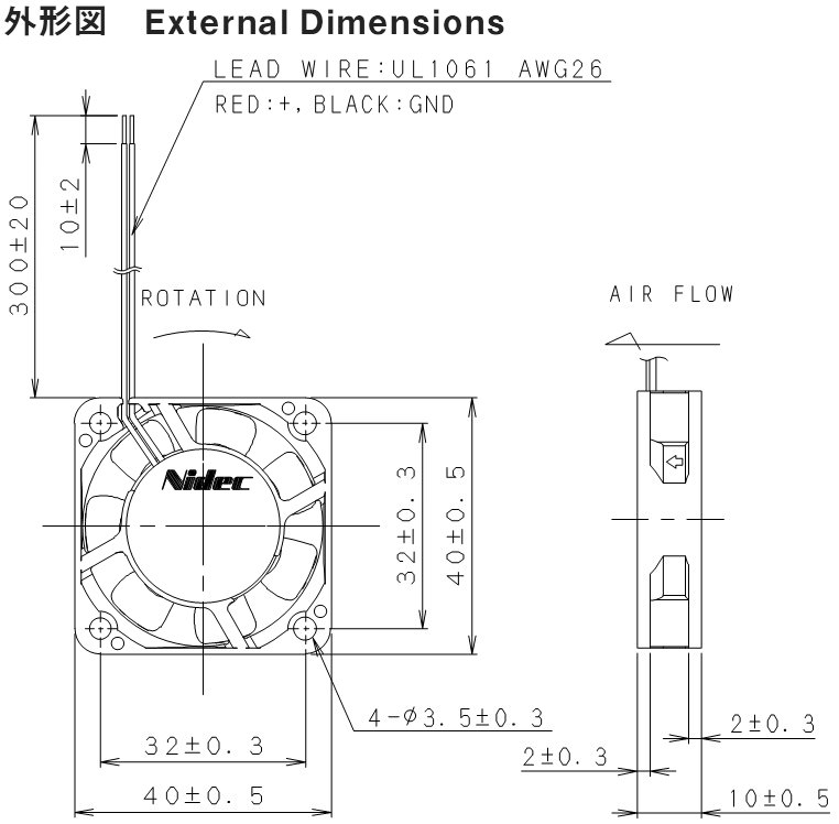
    The fan 40x40mm (outer dimensions) with main inner circle 38mm and 31mm just screw hole to hole distance. The overall wall thickness of the sample fan is 1 mm and all the holes are directly next to it.


    Edit: The sample of Takei hits it accurate I think.


    Markus

  • Link to post
    Share on other sites

    Posted · Pleas CREATE This for ME

    edit: Oops, you posted in between. Looks like your measurements are a bit different from the image above. I'll fix that later.

    Dang, I was off by one mm on the hole distance. I guessed 33mm :p

    Not sure what you want to do with the mounting holes for the fan. You said 5mm (which is what I've put on the model) but the spec sheet above calls for 3.5mm. Also, do you want it like it is now or do you want the screw holes to go all the way through the shroud? If it was me I would probably make the holes 2.8mm and use an M3 screw to hold it in place.

    Anyways, here's what I have so far. It's late now so I'll keep at it tomorrow:

    https://www.dropbox.com/s/d2k14jeepe71nlk/cover.STL


  • Link to post
    Share on other sites

    Posted · Pleas CREATE This for ME

    The fan-example from Takei is certainly more accurate.

    The screw holes must consistently have 5mm, otherwise my special screws would destroy the fan and or the holder. But I have a Dremel and can drill if necessary.

    I can the object in one piece 210mm long Print, I think. Let's see if it works. If I sink the object, I would get the missing 20 mm, then I can stick it together. Plug it would certainly be nice.

    The sheets are identical, but are mounted differently. To the left in the printer, the wider area forms the front and on the right the narrower surface. So I need the sheets in two versions, due to the air-inlet openings.

    Markus

  • Link to post
    Share on other sites

    Posted · Pleas CREATE This for ME

    Ok, then I will keep the dimensions I used.

    Don't you think printing it like this would work? That way nothing needs support.

    coverPrint

    I will create another one with the air inlet on the other side.


  • Link to post
    Share on other sites

    Posted · Pleas CREATE This for ME

    Ok, I've made the second one and slightly modified the first one. Tell me what you think.

    https://www.dropbox.com/s/d2k14jeepe71nlk/cover.STL

    https://www.dropbox.com/s/u0atb9frqgollyr/cover2.STL


  • Link to post
    Share on other sites

    Posted · Pleas CREATE This for ME

    Hello IRobertI

    I just looked at it, and I can not wait to keep these things in my hands. As it stands now, it almost meets my expectations. As it is now positioned on the platform, it will be best to print, I think. I'm going to print it, probably Saturday or Sunday.

    But:

    I print Skirt-lines around the object, 210mm length seem to be the maximum possible. Without Skirt it fits, but I need a clean start, I believe. Maybe it also works if I print somewhere a small object next to it. I need for each cover so possibly two parts or I renounce 20mm length, let's see how it looks.

    In the meantime, perhaps you could:

    - The cavity of the air channel, the volume, please zoom something, so stretch the air duct 5-10mm upwards.

    - A two-part alternative, maybe stuck to each other, please create.

    I do not know how time-consuming it is to integrate the Ulti-Robot on the fronts flat, but that would be very interesting for me.

    Markus

  • Link to post
    Share on other sites

    Posted · Pleas CREATE This for ME

    You can change how close to the object cura prints the skirt, maybe that helps?

    I don't understand what you mean by "zoom something". Do you just mean I should increase the size of the air inlet?

    I'll wait with making a two part model until you've tried printing it on its side, rotated 45 degrees. I think it will fit. (you only need to print part of the first layer to find out I think).

    How do you mean integrate the Ultirobot. Using the whole 3d model (then you have to print standing up) or doing an emboss of the graphic?


  • Link to post
    Share on other sites

    Posted · Pleas CREATE This for ME

    I try to explain it better. If it does not work, then I paint you a terrible picture that is certainly a work of art. :mrgreen: :oops:

    Imagine that the cover is already installed. I just want the air duct inside stretched upwards slightly, so that a slightly larger cavity is formed. The front air intake remains unchanged. The basic positions of the air ducts are as accurate as desired.

    And the Ulti-Robot could be recognizable as an outline, contour, or relief. Basically me any idea is welcome, only the outer dimensions of engine covers must be close to those of the originals. :-P

    I'm going to make a sample print, according to your advice. :cool:

    Markus

  • Link to post
    Share on other sites

    Posted · Pleas CREATE This for ME

    It's more than likely just me being stupid. Is this what you mean? :p

    artwork


  • Link to post
    Share on other sites

    Posted · Pleas CREATE This for ME

    Correct, Yesss, Exact...

  • Link to post
    Share on other sites

    Posted · Pleas CREATE This for ME

    Alright cool. I'll see what I can come up with regarding the Ultirobot.


  • Link to post
    Share on other sites

    Posted · Pleas CREATE This for ME

    With fewer Skirt-lines close to the object it fits, so it should not be necessary in two parts.

  • Link to post
    Share on other sites

    Posted · Pleas CREATE This for ME

    Big bad horror, damn it... :???:

    I started to print and already at the first Skirt It has cracked loudly, then a second time. I believed that the glass plate was broken. Before the third time I was able to locate the cause, the rear (right) glass holding bracket collided with the fan plate from the print head. I had the fan-plate, not exactly aligned horizontally.


    To avoid further problems, I immediately canceled the printing. But the machine ran merrily for a while, until finally arrived the desired behavior.

    Sure, I was to blame. But if I cancel a print job, the machine has to respond kindly. Sometimes created for me the impression that the machine commits suicide ...

    Now on the second attempt everything is better. The first layers are and look fabulous. I think I let the non-final part still print to the end. :-P


    White LED's I have to order, there must be lighting inside... :mrgreen:


    Markus


  • Link to post
    Share on other sites

    Posted · Pleas CREATE This for ME

    Ouch, good it worked out in the end.

    Well... I've spent a while on that damn robot. I've said it before and I'll say it again, that robot is bad for printing. I finally got the logo into SolidWorks (Photoshop -> Inkscape -> SolidWorks) and tried making a cutout from the back. I stopped the cut 0.4mm from the surface so that an LED from the back would make the logo show up when the light is on.

    cutout

    But, cura can't print it. The details are too small. I'll try making the robot bigger but I think it will look stupid.

    edit: Nope, details are still too small.


  • Link to post
    Share on other sites

    Posted · Pleas CREATE This for ME

    There's no hurry, I now print the two existing cover, with 33mm/S, it will take some time. :oops:

    In the picture, the second attempt is to see.


    Earlier on the print abort, during the cool-down the print-head moved still almost a minute. And I could see that my experimental extruder motor even at 160 degrees almost clean-looking filament lanes laid, damn good part ... :mrgreen: I think my UM2 has actually now a pressure-head and no Print Head. :???:

    Maybe you use for the UM-Robot, similar contours as they are seen on the side walls of the UM2. :cool:

    Markus


  • Link to post
    Share on other sites

    Posted · Pleas CREATE This for ME

    The left side is already finished and looks almost anywhere good. There are a few minor mistakes, but that has nothing to do with the design. Currently I print the right side a little faster and hotter, it looks a bit better.


    A black stripe is seen, probably a hair or a contaminant in the filament, or whatever. And you can see where the print head without printing has traveled through the material, it's just transparent material and I have no idea if something can be improved. I will later simply print this part again with slightly different settings.


    Once again went wrong the first start for the second part, and I was back blame. Before starting I had leveled the print bed too close to the nozzle and my experimental engine has simply pushed the Bowden with clip from the feeder housing. Well the problem was quickly resolved and it could go further.


    Markus

  • Link to post
    Share on other sites

    Posted · Pleas CREATE This for ME

    Oooh, nice to see them printed :) I had some time to sit down today and try to get something better with the robot. Here's a render I did as an experiment. Wish I had seen your post before starting the render so I could've matched the colour :D

    What do you think about this idea, looks good? Bad?

    coverTestRender


  • Link to post
    Share on other sites

    Create an account or sign in to comment

    You need to be a member in order to leave a comment

    Create an account

    Sign up for a new account in our community. It's easy!

    Register a new account

    Sign in

    Already have an account? Sign in here.

    Sign In Now
    • Our picks

      • UltiMaker Cura 5.8 Stable released 🎉
        In the Cura 5.8 stable release, everyone can now tune their Z seams to look better than ever. Method series users get access to new material profiles, and the base Method model now has a printer profile, meaning the whole Method series is now supported in Cura!
        • 5 replies
      • Introducing the UltiMaker Factor 4
        We are happy to announce the next evolution in the UltiMaker 3D printer lineup: the UltiMaker Factor 4 industrial-grade 3D printer, designed to take manufacturing to new levels of efficiency and reliability. Factor 4 is an end-to-end 3D printing solution for light industrial applications
          • Thanks
          • Like
        • 3 replies
    ×
    ×
    • Create New...