


avogra
-
Posts
303 -
Joined
-
Last visited
-
Days Won
3
Content Type
Forums
Events
3D Prints
Posts posted by avogra
-
-
Zur besseren Wärmeübertragung.
Soweit ich weiß, hat das nichts mit Wärmeübertragung zu tun. Die Kupferpaste wird immer dort eingesetzt, wo verschiedene Metalle bei erhöhten Temperaturen aufeinander treffen um Korrosion zu vermeiden. Da Kupfer ein besonders unedles Metall ist, wird nur das Kupfer in der Paste angegriffen, anstatt dass von den beiden zu schützenden Teilen das unedlere korrodiert.
-
During insert material ( or.. I only use change material), I too have clicking but printing works fine. I got to conclusion for myself, that Ultimaker intentionally reduce the feeder motor current during insert material in the case of bad filament or so.
-
I just looked over my post with the drawing again. Unfortunately I used the word "wall"-thickness there. That is not correct and might confuse. Actually it should be shell-thickness.
-
@mbmast, you haven't yet understood the concepts of slicing.
It would be helpful if you give us some more information: Which program do you use to create your model? Give us some screenshots of your settings in Cura, as well as screenshots of the model in standard view and in sliced view. Show us a screenshot of those inner structures so that we know what you are talking about.
I think what I've been told in this thread is the following:
1. If the walls of the model have zero thickness, then you must specify something for the shell thickness (and it should be a multiple of the nozzle diameter). And I find that this works, so long as the model has no internal structures. It does not work if the model has internal structures (perhaps because the model is a blend of surfaces and solids).
No, that is not right. I guess in the software you use to create models you can define a wall thickness, but Cura's parameter shell thickness has nothing to do with it. Furthermore in the STL file format there is no information stored about any thickness or walls or such, it only describes surfaces enclosing your model volume. That is also one of the problems of the format for 3D-Printing: It is possible to create STL-files which have no clear inside and outside. That is what X-Ray-Mode is for, there you will see such errors.
Maybe the word surfaces is better to explain how slicing works. For Cura, it doesn't matter if those surfaces are inside like a drilled hole or if they make the external boundary. (There is an exception to that, as Cura by default removes all surfaces that are entirely enclosed inside the model).
From the surfaces inwards, Cura lays the shell lines, so the "shell" can easily be in your model.
-
Funktioniert der I2K Ring auch mit PLA? Ich dachte auf der Homepage stand dass er dafür ungeeignet ist.
-
@CheaT, eventuell ist auch das bed levelling nicht perfekt. Ich finde ja die vorgeschlagene Methode mit dem Papier nicht so toll. Hab mir eine Fühlerlehre gekauft fürn paar Euro. Wenn ich damit den Abstand auf exakt 0,07 mm einstelle, bekomme ich perfekte Obeflächen (Theoretisch sollten es eig. 0,1 mm sein).
Was auch hilft: Die erste Schicht etwas heißer drucken, z.B. 210°C bei PLA und dann in den nächsten Schichten runtergehen. Damit wird die Unterseite auch noch schöner geschlossen.
-
Hey @mbmast,
I tried to paint something up
 Maybe it helps to understand how slicing works. Another wording of what @peggyb said: You give Cura a solid model and it will hollow it out to save material. Wallthickness is how much material is left vertically, bottom-/top-thickness is how much material is left horizontally.
-
 1
1
-
-
@cloakfiend, I will have a try

In order to unplug the heater from the electronics board, you need access to the top side of the electronics. To achieve this...
1.) Remove the left motor cover. It is mounted with 2 screws, one through the back, one through the left side.
2.) Lay the UM2 on it's left side for easy access. Move the heated bed up to access the screws in the bottom.
3.) Remove the electronics cover cage, which is secured by 2 screws. ( You might already have done this for the PT100). Grab the nuts on the other side to prevent slipping.
4.) Open the 4 screws holding the electronics. They are the ones sitting in elongated holes. Be careful not to lose the small black spacers, maybe grab them with pliers while opening the screws. The electronics board is now loose but some parts like switch and power connector still stick through the backplate.
5.) Carefully pull the electronics board out of the backplate and swing it onto the table. You see a green terminal block where the extruder heater and the bed heating are connected. There seem to be different versions of the terminal block. According to the assembly manual and the schematics on github the heater wires are fastened with screws. open the screws und pull the wires.
My UM2 from Oct. 2015 instead has a spring loaded terminal block. Use a flat screwdriver to push the first orange clip and while holding it down, pull the first wire. Repeat for the second wire.
6.) Make sure, that the strands of your new heaters wires are neatly in parallel or in other words, make sure there are no single strands sticking away.
7.) Press the first orange clip again and while holding it down, insert the first wire into the terminal and repeat for the second wire. If your terminal has screws, just insert the wire and fasten the screw. The 2 wires are interchangeable so it doesn't matter which wire goes in first and second place. Make sure, that all the strands go into the terminal insert.
8.- x.) remount the electronics and covers in reverse order. (I don't fell like describing it all the way back
).-
1
-
-
@avogra, thank you! We did our best to make them conclusive.
The manuals have come from a long way
Are you specifically asking on how to remove the heater from your electronics board when you replace it by a 35W?
Yes, that is the question. It is different from the PT100 as the heaters have open wires instead of a connector so there are some extra steps involved.
-
@cloakfiend, If your temp sensor shows lower readings than before, I would suspect that you now have to set higher values to get the same real temperature again?
I changed to the ollson block yesterday together with new pt100 and 35W heater and measured the actual temperature inside the nozzle before and after. Used a multimeter with one of those K-type thermoelements that have only a tiny solderball as the tip.
I was really shocked that my original setup set to 200°C actually was at 223°C
 And I usually printed at 205..210°C The new setup is at 208°C when showing 200°C. Same results with a different thermoelement + multimeter.
@SandervG, the tutorials for changing the Olsson Block and PT100 are really great!! Maybe you want to add one for the heater too? I was struggling a bit how to detach the heater cables from the PCB. I tried to look up the type of connectors in the schematic to see if they are 2 part and I just have to pull. But the schematic seems to be out of date as the connector was different. In the end, after detaching the pcb, everything went fine and my printer is running great again

-
@Labern, then it probably doesn't make any difference at all :PI didn't get the PT100 out of my old block with only 200 hours printed and maybe 10 hours thereof above 210°C. Anyway, I'm not planning to exchange it in the near future. Installed the 35W heater too at the occasion so I hope I won't have to touch my hotend anytime soon.
@neotko, thats exactly what I did in the end
-
1
-
-
Ok, I will give the copper paste a shot
Thank you both!Don't know which answer to mark as best :( I think no single one is helpful directly under the question. Is that ok for you?
-
@Labern, are you referring to conventional thermal grease or to copper paste?
-
Thank you @Dim3nsioneer. So you just use conventional thermal grease like the one you get for computer processors or did you use something more temperature robust?
-
I have poked around and came to the conclusion that thermal grease is hard to find for temperatures above 140..180°C. Instead I think of copper paste now
 Is that even more stupid or just perfect or... ?
 -
Hey everyone!
I'm going to install my new Olsson Block today and I was wondering if it is a good idea to add some thermal grease? The installation manual doesn't mention it but it might be helpful. Did you do anything like that?
-
Wenns sowas aushalten soll wie schürfen über Asphalt (?) harte Schläge, würd ich ja Nylon empfehlen, aber das ist halt schon recht unschön zu drucken. Bisher hab ich nur Taulman Bridge und 230 probiert, das neue Alloy 910 soll ja deutlich einfacher sein. ABS hab ich noch nicht probiert, soweit ich weiß ist es zwar robuster als PLA aber jetzt auch nicht unbedingt flexibel.
-
You might want to have a look into this great Troubleshooting guide:
http://support.3dverkstan.se/article/23-a-visual-ultimaker-troubleshooting-guide#underextrusion
-
I wonder what version of Cura you are using? Basis tab should have the extruder temp under Speed and Temp., unless it has been moved in one of the later versions. I cannot see it anywhere and it is err vital!
When you set GCode-Type to "UltiGCode", Cura expects you to set the temperature on the printer and hides them.
-
Könnte mir vorstellen, dass durch die vielen Retractions der Feedermotor ziemlich warm geworden ist und dadurch das Filament aufgeweicht hat. Das wird noch verstärkt, wenn auf dem Weg zur Düse zu viel Reibung auftritt und der Motor härter arbeiten muss um das Filament zu schieben -> Düse teilweise verstopft, Zustand PTFE-Coupler, Bowden-Schlauch nicht ganz im Coupler, ...
Falls hier alles passt: Langsamer drucken, damit der Motor mehr Zeit zum Abkühlen zwischen den Retractions hat. Zusätzlich einen Turm drucken, so dass in jedem Layer etwas mehr Filament verbraucht wird und nicht immer dieselbe Stelle im Feeder hin und her geschoben wird.
Das sind ein paar Sachen, die mir auf die Schnelle einfallen
-
1
-
-
hmm, the post before my last one has vanished
it was:
does it make any sense to have a nozzle that isn't rigid or at least has a flexible tip.
-
Or what about that: a closed nozzle in the shape of a sphere or flat with rounded contour. you would use that after a print has finished to go over the top again, slightly remelting your print to getting a perfectly flat surface.
-
I recently had an idea that might improve the nozzles in general: I have a soldering station by JBC which has a quite fancy technology. In contrast to conventional soldering irons, the heating and the temperature sensor are part of the exchangable tip. Due to this, they have to heat a very small mass and have immediate feedback, so they have super tight temperature control and can react quickly on changes. there is a YT-video around, where someone dips a 350°C tip into cold water and it only drops by 30°C. At the same time, replacement tips cost ca. 20..30€, so the technology seems to be cheap to manufacture.
This isn't exactly a possible nozzle for the machines out now though :( Just thought, the idea remotely fits the topic
-
what about some nozzles with similar size to 1mm but with wire-cut crazy shapes like piping tips
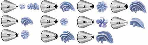
At larger layer heights it could give some interesting effects.
This sounds like a fun project. What we need is some nozzle blanks ( solid right to the top of the thread ) that we can experiment with.
Ones that work best for flexi materials is definitely at the top of the list seeing there are some different hard ones available.
haha, great
maybe add to that some calligraphy nozzles
 Maybe it helps to understand how slicing works. Another wording of what


 And I usually printed at 205..210°C
 Is that even more stupid or just perfect or... ?
Fill thickness only with perimeters
in UltiMaker Cura
Posted
Did you try to set infill to 0 and disable top bottom fill and then increasing shell thickness really high? that should give you perimeters only. but I guess that is not all that you are after?