


Stefania Dinea
-
Posts
97 -
Joined
-
Last visited
-
Days Won
3
Content Type
Forums
Events
3D Prints
Everything posted by Stefania Dinea
-

THE ARCHITECTURE OF 3D PRINTING - 07 STL EXPORT FROM REVIT
Stefania Dinea replied to Stefania Dinea's topic in Industries
@SandervG - I usually export in binary - never questioned this system since it was never really explained, from other software i control the number of polygonson export, but Revit does not have this option -- buhu! -
@kmanstudios DAAAAAAMN!!
-
Hello, I gave up trying to print it flat, and went for the obvious solution and printed it standing with pva added just touching the build plate, oh well, lost like 12 hours but rather have a success than insist on it working another way. Thanks for the useful tips.
-
The idea is not to. I also switched to single extrussion - and it is weird because if you measure the glas plate you have 270 ???
-
Anyone know how to hack the settings to be able to print this size? Thanks.

-
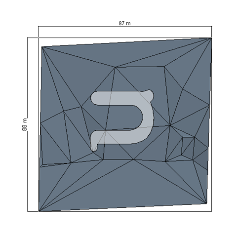
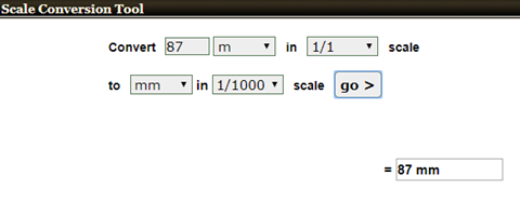
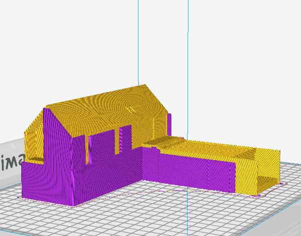
I am Stefania Dinea, an architect who mixes 3D printing, VR, parametric design and blogging daily and I will share some of my 3D printing tips & tricks with you. This series is my overview about the process and my work-around. Please feel free to comment and add. PREVIOUS POST: THE ARCHITECTURE OF 3D PRINTING - 01 TOPOGRAPHY THE ARCHITECTURE OF 3D PRINTING - 02 MASSING THE ARCHITECTURE OF 3D PRINTING - 03 TOLERANCES AND SNUG FIT THE ARCHITECTURE OF 3D PRINTING - 04 ENTOURAGE THE ARCHITECTURE OF 3D PRINTING - 05 HIGH RESOLUTION BUILDING FACADES THE ARCHITECTURE OF 3D PRINTING - 06 INTERIOR DESIGN 7 STL EXPORT FROM REVIT The most confusing thing that you need to have covered is exporting the stl. Starting with revit 2018.3 Revit had the stl export as an add-in, however for those of you who work in older versions here is how you go about it. Go to the X (the blue and white one)- to open Autodesk app store Search for stl and the following apps will appear: You will want STL exporter version x – corresponding to the version of Revit you own. Remember it will export all elements in the view – if you don't want to see something – hide in view, and if you want to see 1 element of out 1000, you can isolate in view. In the export settings, pay attention to the units the export is done in, that will play a major role when scaling in cura –and it will help you see where you are at. For the site I will use meters. Also, it will be good to be constant, if you start with meters, you need to keep it like that for the whole project so you don't get confused. CURA 1. SCALE We all know in architecture scale plays a big role – therefore this is another aspect that you need to pay attention to. Taking alternative 1 into consideration and our topography/massing examples we know the following: Our example file in x-y is 87x88 m I have exported, as I said using meter units instead of mm And in cura we will see the following: Also, one can use online scale converters such as: http://www.scalemodelersworld.com/online-scale-converter-tool.html We therefore can conclude that our model is in 1:1000 scale at 100% in cura And 200% will take us to 1:500 However, when we talk about site plans, a 1:400 would be desired therefore a 250% scale in cura would be ideal, however the site is a little too big for that, so, we will go back to revit and readjust with the section box. But first, you can use the scale calculator to see what maximum sizes you would need. So rescaling the section box, you get to print in scale 1:400 and fit in the building plate. This is all for this post, I am slowly moving into the Cura tips and tricks (better say my tips and tricks) - as usual feel free to say what works for you, what is your work-around in your main software or in Revit. Also guys and girls, what are your expectations for the summer - should I keep posting or should I take a break until august? up to you! NEXT ON THIS SERIES: 08 SINGLE EXTRUSION


-
I got them out - @SandervG? does it work for you?
-
@SandervG - damn, I see what you guys did there - that was a hell of a loophole - specially on the formula 1 car - compliments to the designer/s ? very smart solution!
-
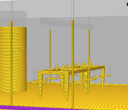
I am Stefania Dinea, an architect who mixes 3D printing, VR, parametric design and blogging daily and I will share some of my 3D printing tips & tricks with you. This series is my overview about the process and my work-around. Please feel free to comment and add. PREVIOUS POST: THE ARCHITECTURE OF 3D PRINTING - 01 TOPOGRAPHY THE ARCHITECTURE OF 3D PRINTING - 02 MASSING THE ARCHITECTURE OF 3D PRINTING - 03 TOLERANCES AND SNUG FIT THE ARCHITECTURE OF 3D PRINTING - 04 ENTOURAGE THE ARCHITECTURE OF 3D PRINTING - 05 HIGH RESOLUTION BUILDING FACADES 6 INTERIOR DESIGN BIM families are excellent however they have an issue, when scaled down they become invisible. Check these screen grabs from the unaltered revit model, and tell me – what’s wrong with this picture? So before you get started, might wanna have a look and see what you need: Looking at the floor plan, we need some kitchen furniture, bathroom furniture, stairs, tables and chairs. Seems easy enough. The bad thing is if you are in the beginning and you have none of these, it will be a little time consuming to create the sets. But before you get cracking, you might want to check what furniture you can use. The Sofa Ottoman is a good example of keep. However her big sister, has lovely little legs which will not do - 2 options, delete and lower the sofa, or delete the legs and extend the sofa with the height of the legs. I will go for option no.2 Same with the side table: Remove the legs, and turn it into a cube would be my next step. Might want to remove small objects like vases. And also, start making your own solid families, like chairs - the ones existing in revit forums are not suitable for printing in such a small scale, the single extrusion will not be able to handle it. Even if you have a dual extrusion, you have to make sure the minimum width is kept. Once you deal with all the furniture you want to illustrate, you go back to the same steps as before. Create a separate view, use a section box to enclose the area you want to print and then you have to make other decisions. So, you don't need to print to see the things you need to correct, importing the model into cura, will do just fine. In this case, i need to cut the model right under the floor and the decide if I want to keep the windows opaque or not. Personally I like to keep the opened, just the frame visible. First you play with the section box and adjust the level of the cut. Even though you deselected the windows and curtain walls in the Visibility and graphics, you might want to make sure you hide them manually as well. Although, sometimes, the exporters won't work as expected, so you might want to take the extra step and hide things from the exporter and or delete the glass in question from the family. This is the result in cura: You apply this mentality for the whole house. Making custom furniture for the kitchen, bathroom and any other elements. Also you might want to consider that for this process you might want to use a 0.1 layer height and print at a lower speed to increase the quality. The examples I will attach below are printed at a high speed 100 mm/s and 0.2 layer height - and as you can see the model had a little bit to suffer because of it. However all these models were printed using PVA and were printed on an UM3. The conclusion for me is that I have to tweek the settings a little bit more, a lower the speed. Also the fireplace printed but it came undone during the PVA wash so I have to revisit the reason why. The reason why the fireplace came undone was because it was a floating element. This is the first time I encounter something like this so what would you do in a scenario like this? When showing off architectural interiors first of all you only show the fixed furniture - kitchen, bathroom, and spaces like living rooms are usually unfurnished. However the question is, would you use furniture in these space? and if so, why? room 1.stl room 2.stl room 3.stl


- 1 reply
-
- 3
-

-
Do they now?! Gotta check!
-
That's how I started a year ago - by placing it where everyone could see it. Good initiative!!
-
@geert_2 we have to rely on manufacturers for colors, we get what they think we want - there won't be a supply before there is a demand - I guess this is the point of this post.
-
The type of printer shouldn't be an excuse, if you can print it on a low end printer you can absolutely print it on an UM2 and above. Some things may require PVA however how you, as a designer, chose to find a work-around will make the difference - a difference that will be seen later on in time and money.Glue, or other types of fixing are all welcomed, however i would recommend they be specified if they are very creative ?
-
Glad my tips can cross software platforms, I forgot about one thing with the mullions, they need to be thickened as well, will come back soon with the correction and example - the model is still in the fish tank :))
-
@SandervG - no, we usually glue them to the laser cut landscape or to the 3d printed landscape. The discs are fine when you want to play arround with them. The wholes in my example were an example on how to go about it. However, my no. 1 choice will always be super glue!
-
@SandervG - structures, things you would like to highlight for sure. I wouldn’t bother with trees to be honest, one could though. Volumes are another thing, if you want to divide by function of building.Maybe I should have a colored example to see how far I can take it ?
-
@kmanstudios haha - you are so right! I remember when I did my Revit certification back in 2013 - I felt so trapped while reading the questions- those things were harder to understand than my Cambridge exam! Also about methods- this is just one way to do it of course, and as for Autodesk software - there are always at least 3 different ways to do this - that is why BIM managements is very hard - because everyone has their own way of working and getting everyone to dance to the same tune is beyond a normal state of confusion.
-
@kmanstudios thanks, glad you like it - you just gave me an idea - I should really send this to them ?
-
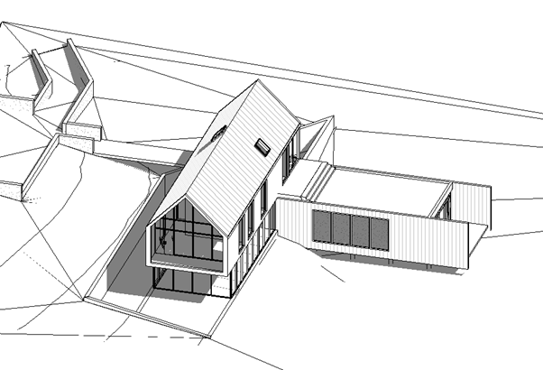
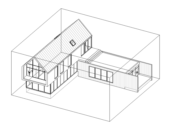
I am Stefania Dinea, an architect who mixes 3D printing, VR, parametric design and blogging daily and I will share some of my 3D printing tips & tricks with you. This series is my overview about the process and my work-around. Please feel free to comment and add. PREVIOUS POST: THE ARCHITECTURE OF 3D PRINTING - 01 TOPOGRAPHY THE ARCHITECTURE OF 3D PRINTING - 02 MASSING THE ARCHITECTURE OF 3D PRINTING - 03 TOLERANCES AND SNUG FIT THE ARCHITECTURE OF 3D PRINTING - 04 ENTOURAGE 05 HIGH RESOLUTION BUILDING FACADES Hello again, I have been away for a while and during this time, being pressed by my two week deadline, I realized that I was spending too much time designing the “Ultimaker house” rather than explaining how to deal with complex projects and hit my end goal – which is to explain my work process. I guess in one way or another we all get carried away at some point and focus more on the fun things. However this is how far I got with it, and I will probably finish it at one point just for fun – but that is a villa and I need some time to patch it all together. However for now I decided to continue these series on the Autodesk Revit sample project which has plenty of everything already in it, and plenty of things to fix and adjust in order to make it suitable for 3D printing. So again, I have to make the site, and create my base. However, I have already explained how I do that in previous posts, so there is no point in repeating. One quick tip though, if you don't want to move the building pad points, one quick solution fix will be to place a vertical shaft/shaft through your site. That way you minimize the number of points you need to add to your floor. To begin, start hiding in view, all the things you do not need: Such as – entourage, furniture, railings. You can do these by either selecting a category in your 3D view, right click – Hide in View – Category. or by pressing V V on your keyboard which will send you direct to Visibility settings. But before you get to serious about these settings, don’t forget to make a copy of the 3D view, dedicated specially for 3D printing. For the easy version, however I do recommend the VV option, deselect everything first. Then begin with the things you want to see, which include – floors, windows, roofs, stairs (in case you have some exterior stairs), doors, columns/structural foundation. Remember, your site is a floor and mass – we will get to that aspect in a minute. Pay close attention to the windows however, you might want to keep just the frame and the mullion for this stage, watch out also for Curtain wall mullions After everything irrelevant was taken out – I am left with this: Here is what is hidden: Now, you might want to look inside the house and see if there are any extra details you might want to get rid of. Remember, section box is your best friend. And as we proceed, we will start hiding in view interior details such as – stairs, interior walls. We will do this to increase the printing speed, taking out unnecessary volume and irrelevant elements that will not be seen anyhow. When you are done with the ground floor, move up a level. You might want to also hide the partition floor as well. The next step is to fill the building with a mass. Why? Because that way the whole building will be considered a solid, and cura will take over by offering the right amount of infill, saving time, increasing quality, and also avoiding epic fails. So you begin by working in parallel – plan and 3D view. In the plan view, Massing and site, In-Place Mass. The outline of the massing, should be ideally be fitted to where the frame of the window begins, that way, when exported to .stl, they will merge as a solid. In the 3D view, make sure you adjust the height of your mass so it fits nicely between the floor and the roof, usually I lower it a little bit more, so it also acts as a base. Before: After: The same thing will be done for the 2 story part of the building, only instead of a plan, I will model the massing in a section. To model a mass in sections – grids may be required, so make sure you have a couple before that. Same principle of the window aspect has been applied for the mass, and in order to get relief details, the massing should be modeled on the center line of the roof and walls. Some small adjustments should be made in plan view and 3D view. Now, the question is how to split this model up? 1. You can print it with site 2. You can printed in multiple pieces For projects like this, if you don’t own an UM3, and you do not have access to a PVA accessible printer, things can get really complicated. For safety reasons, I will always recommend splitting it up. Since this section focuses on creating more high resolution building facades, which should highlight window and access placement, I think it is safe to export the building as it is illustrated above. And this is how it looks in Cura, clean, easy to print. This layer section is made to specially highlight the reason why the building was filled with massing, which is a considerable time and material saver. Not to mention you don’t want fragile mullions and dripping floors from lack of support. Having an UM 3 or above, does come in handy, whether you are a fan of breakaway or PVA it does save a lot of time and cures a lot of headaches – the same model can be done with a single extrusion printer, but not as nearly as easy. For this scenario I used PVA support, which is my favorite, mainly because I only drop it in the fish tank when I am done, and no extra work is required on my behalf. To save time and material (again) I only use the Support touching the build plate function. Also a preview of the site plus building model attached if you feel like printing the file with the site. I will come back with some photos of the results as soon as I get them out of the printer. ? RESULTS: Now, as you can see from the photos, the mullions are not obvious - so one thing I have mismanaged was thickening the mullions. That is something you also need to watch out for. You start by selecting all in a 3D view > go to filter > select just the Curtain Wall Mullions > Modify > Unpin >Properties > Edit Type > Create a new profile. Right now the profile is 40 mm which in scale will be 0.4 mm - a detail so small it will not be perceived as an obvious feature. I will change it to be 2 mm , therefore I need 100 mm on each side of the profile. Remember to do changes like this on a decentralized file, you don't want you actual BIM project to suffer. Here are my new settings: This is the result, it may look chunky in a 3d view, but I believe in a 3D print it will be just right. If you have parametric windows, you might consider doing the same for that as well. The Revit result looks like this, now time to export and see how it performs in Cura. So now, it looking more to where I wanted it to go. Again, will come back with updates as soon as I get to print it. If you have no patience, I have attached the file below: Autodesk house complete - v2 The result with the improved mullions: NEXT ON THIS SERIES: 06 INTERIOR DESIGN Next time on the blog it will be the last blog that has 100% Revit content. BIM families are excellent however they have an issue, when scaled down they become invisible. Check these screen grabs from the unaltered Revit model, and tell me – what’s wrong with these pictures? Autodesk house internal.stl autodesk house with site.stl Autodesk house complete.stl Autodesk house complete - v2.stl


-
haha - some girls do their nails at work, I use superglue and tweezers while revit is loading :))
-
Yea - why overcomplicate?!
-
Hej, Sure I can share, but nothing special though. The height of both the base and the silhouettes is 1.2 mm, printing speed 70 mm/s , layer height 0.1, nozzle 0.4 zI printed them separately because I initially misunderstood what my coleague wanted - soo superglue ftw. Material - ultimaker PLA. They were made from simply extruding autocad lines - rhino ftw! Pretty basic.
-
@DanielHolmSweden Super glue works fine,stay away from hot glue though. I really like the idea of lowered walls on the interior. I am also wondering what is your layer height and youy top/bottom layer height? Thanks for sharing.
-
@Florisvh and @SandervG Scale 1:100 little people ? I made them for a workshop one of my colleagues had, the base was optional so the could move them around. Total printing time 2h.


-
Hello Sander, White, wood and carbon - those would be my top 3 choices, I had a thing for the natural PLA, which gives a small, too small, transparency. I chose to limit the color choice to white just so I can better control the quality output and limit the settings - it worked fine for the past year and there were no major issues with the UM printers in our office. However, in the future, we have agreed we like matte colors - including matte white, the shinny plastic can end up looking a little cheap and/or cartoonish and conversations about having custom made filament in our company colors have arisen. And if we have to pick a color - it would probably be Stockholm white.


