


Stefania Dinea
-
Posts
97 -
Joined
-
Last visited
-
Days Won
3
Content Type
Forums
Events
3D Prints
Everything posted by Stefania Dinea
-

THE ARCHITECTURE OF 3D PRINTING - 04 ENTOURAGE
Stefania Dinea replied to Stefania Dinea's topic in Industries
@Alex L awesome!!! -
THE ARCHITECTURE OF 3D PRINTING - 04 ENTOURAGE
Stefania Dinea replied to Stefania Dinea's topic in Industries
@Alex L .... NO COMMENT ! ..ok just one: I can't believe it !!! I am starting to really doubt Revit! However, it is a problematic software for 3D printing, so I guess my tips will be useful for some, and your valuable input very useful to the other side of the camp. Is that little human 3D printed on a UM? please share settings if yes. -
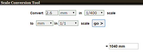
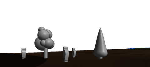
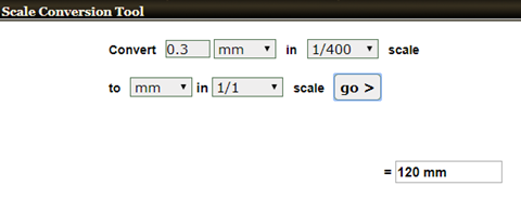
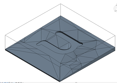
I am Stefania Dinea, an architect who mixes 3D printing, VR, parametric design and blogging daily and I will share some of my 3D printing tips & tricks with you. This series is my overview about the process and my work-around. Please feel free to comment and add. PREVIOUS POST: THE ARCHITECTURE OF 3D PRINTING - 01 TOPOGRAPHY THE ARCHITECTURE OF 3D PRINTING - 02 MASSING THE ARCHITECTURE OF 3D PRINTING - 03 TOLERANCES AND SNUG FIT 04 ENTOURAGE Basic entourage consists of the following: Human figures in scale, trees and vegetation, and vehicles. So what would be the best approach to this? Especially when you are dealing with a sloped terrain – you also have to remember that super glue is your best friend but it does not always give out the best result in terms of optimal efficient solutions. One of my tips is to place holes in the site (floor in revit) and make little support extensions/pins for your entourage of choice. So how thick should a pin be? Remember the 2 mm min thickness I was talking about? Well that would be it – 2mm in scale in 1:400 + offset of 0.3 mm. So in scale that should look like this: Support system diameter: Support placement diameter: This is how the site looks like after perforation: To do now entourage – one option would be to model in view, another would be to use a family to model specific entourage. One thing you cannot use are the families already included in Revit (unfortunately) specially when it comes to entourage. To look for inspiration, there are multiple options, in terms of sketching, and as I said before, you are only limited y imagination. So to get started you might want to use the following keywords in your google search: people silhouettes and architecture tree sketches and you will find example such as: So pick what suits your own project, your style and maybe you even have your own design. Now to continue with Revit, cut a section through one of the placements spots and insert and image of one of your desired human silhouettes once you have decided on one type and click on model in place. The simplest way to go around things is to just trace and extrude. and it might look bulky due to the scale you are working it – but remember that in the final print it will be quite small and fragile. A perspective preview of the result: I would print this item flat, however the issue is as follows: If you check the top view, my base model might be problematic and my single extrusion is impossible. The solution is to alter the base. If your model seems to thick and chinky, you might consider printing it on the side, and cut it in half. Just look how small it is at scale 100% in Cura - it's a game of spot the model (it's the very small yellow dot in the middle ) (it's that very small yellow dot) However, in scale 1:400 (250 in cura) it will look a lot bigger, not by much though. After the first print with recommended Cura setting for extra fine I discovered that my 0.3 tollerence in Revit was too little. So with these general dimensions in Cura, my print pin was just the exact fit of the diameter whole – therefore inadequate. To avoid going back to Revit and making alterations, I went for a modification in Cura. As follows, by making sure that Uniform scaling is unchecked – in the end, the only thing of importance that needed rescaling was the diameter of the base and not the height. Running a test print and seeing that this tolerance worked I remodeled the initial scalable human silhouette – and took if for another test print. The same principle applies to modelling tress, you can make them as a flat 2D extrusion or a 3D volume. In the image below are two examples: For efficiency reasons I do recommend you model them as a family type, so you can reuse them in multiple projects. And I do recommend you make a parametric family so you can change the level of detail according to scale. But more on that in another blog. For now I will print a little army of trees so my landscape will look something like this: As you will notice in my final prints photos, I am not a patient person, and in this industry is hard to be, as everything is last minute and deliveries have a yesterday deadline on them. No matter how fast the machines are working if it's not instant it is never fast enough. However, please remember the time when everything had to be made by hand and delivery took forever on various materials needed to produce a model – I don't know about you, but I sure don't miss it – not to mention the cost. Nowadays time is generally consumed by 3D modelling – that is why I am a huge fan of BIM – if you have a proper BIM model, adding an extra as a 3D print should take no time at all to adjust, as you will see in the following chapters. Also, how small can you print entourage? NEXT ON THIS SERIES: 05 HIGH RESOLUTION BUILDING FACADES human.stl site for landscape.stl tree1.stl tree-2.stl


-
THE ARCHITECTURE OF 3D PRINTING - 03 TOLERANCES AND SNUG FIT
Stefania Dinea replied to Stefania Dinea's topic in Industries
I will post the entourage today or tomorrow, since I will be away the next weeks, so i am unable to handle it from Friday on, just a quick peak at comments and debates. I used it from the a swedish reference, in the sense that site plans are usually delivered scale 1:400 for building permits - and this first chapter is about that, of course you can go even smaller, like 1:1000, but this was my choice for now. So it has some base in my professional reality. Yes, I always start with .3, I have noticed that with .3 I can never fail, weather it is buildings or jewellery. But again, that is my experience. -
THE ARCHITECTURE OF 3D PRINTING - 03 TOLERANCES AND SNUG FIT
Stefania Dinea replied to Stefania Dinea's topic in Industries
Hej @SandervG and @Alex L, in my xp, revit families do become too small to print, by that I refer specially to furniture, which in general are very thin, like 12 mm thick , because as a good BIM family, it respects reality. Scaling it down makes it vanish in thin air and therefore unprintable. However, next I have entourage on the plate for the what can your software print "challenge" Alex, the model looks greats, and I said before - so gelous. -
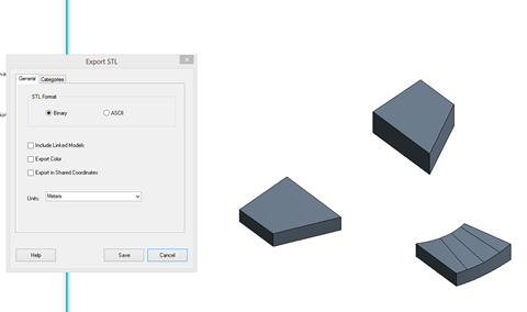
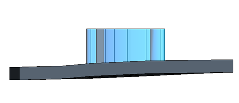
I am Stefania Dinea, an architect who mixes 3D printing, VR, parametric design and blogging daily and I will share some of my 3D printing tips & tricks with you. This series is my overview about the process and my work-around. Please feel free to comment and add. PREVIOUS POST: THE ARCHITECTURE OF 3D PRINTING - 01 TOPOGRAPHY THE ARCHITECTURE OF 3D PRINTING - 02 MASSING 03 TOLERANCES AND SNUG FIT Now that we know we will be printing in scale 1:400, would be good to be able to use one site for all 4 previous versions. To print in scale 1:400 we need to alter the site, for that a simple edit in place of the floor slab we just did will do, or even easier, make a section box. To print in the specified scale, we need to know how much will that translate to in scale 1:1 , also take into consideration the printing size - 180x180mm for the UM3 dual extrusion mode on. All is left to do is introduce the factors in an online scale converter – or if you are up for it, old school math. This being said, I will make sure the section box will be adjusted to box 72 x 72 m. Tip for this action is to work in parallel with the plan and the 3D view. So how much is that in cura? As a percentage? We will export again in these settings, and as said in the cura tips&tricks section, you will see that if you use the xtl exporter and you set it in meters as export settings you will need a 250% scale up. But this topic is about snug fit, for a snug fit you need to allow a tolerance offset, just like in reality. In the case of 3D printing it is between 0.3 and 0.5 - a skill you will learn to master by experience, trial and error. For this exercise I will use a 0.3 offset in scale 1:400. As you footprint might remain the same, and your design will probably change specially in concept stage, begin by offsetting from your border line. The result will look something like this: However, you are not done yet, I generally recommend that the bottom is not let empty, but also as a part of the site, for that we will do another floor to cover the area under the proposed model. In my case, it so happens that the new floor is placed under Level 1, and Level 1 is my zero floor, which works for me. If the scenarios would have been different I would have just offset the new floor in a + or – direction from the Revit Properties menu bar. This is a section from Alternative 1 – you might want to check all alternatives just to make sure you don't need any extra information input. I have noticed that the sides of my new cut-out are at level 0, therefore an adjustment is needed as well on the edges. Same routine as when you did the sloped floor – Modify sub elements – and add the desired point height. The new result will look something like this: So now you are ready to export the site and each option individually. The site will be exported from Main Model, in meters as units. The same will be done with all the design options, one way to export any Revit element individually, for 3D printing is to Isolate Element in view. Once your model looks like this, you are rready to export. Repeat the same rpoceedure for all elements. However in the case of option 4 we have extra space between the volumes, you might want to fill in those extra gaps now. Place the new floor components also in Design option 4. Don't forget to adjust the height and also to place the offset mentioned before. Isolate the elements in view and again, export them separately from the rest. 3D PRINTED RESULT: NEXT ON THIS SERIES: 04 ENTOURAGE FILES FOR DOWNLOAD: site.stl alternativ 3-4.stl alternativ 2-4.stl alternativ 1-3.stl alternativ 4-3.stl alternativ 4 - extra site.stl site.stl


-
@Alex L looks really good and 22 hours is a good time for that print.
-
THE ARCHITECTURE OF 3D PRINTING - 02 MASSING
Stefania Dinea replied to Stefania Dinea's topic in Industries
@Alex L so gelous right now :(( -
THE ARCHITECTURE OF 3D PRINTING - 02 MASSING
Stefania Dinea replied to Stefania Dinea's topic in Industries
@Alex L I guess the most important thing for us would be how to best prepare a model for export as an efficient .STL file - Things like curtain walling seem far too complicated for Cura (when opening in Sketchup they are made of many many surfaces and Cura fails to read this as an element which it can slice properly) So it would seem things like this need tuning to simple solids before exporting. I have printed a lot of curtain walls and windows elements and very thin details, and this topic will be included in my :how to: sections to come. I personally am not a sketchup user, and I personally refuse to touch that software 1. it's heavy on import 2. the 3D printing hassle killed it for me. However i do use a lot of rhino and grasshopper because I can import it into Revit and all that jazz. Like the hexagonal CW - that was a pain to model, not so much to print, but not impossible - now I can do it faster and more precise.Will explain in a later post. However, I have a manual I need to look for that I usually throw at my sketchup using colleagues - and I believe I can share that with you since it's online open source. what I can tell you for sure is that you are correct, you need solids!!! You should definitely give it another try (not everyone is moving to Revit! ), it is getting more like sketchup and now has integration with grasshopper which is pretty exciting - I just need to keep playing with it to get the best out of Cura. Which isn't always easy when running live jobs. No matter which software I use, I believe some of the tips are standard. The same method can be applied to multiple tools. Archicad I will open at one point, however -sketchup - long term personal grudge :)) I am sorry - not for me! I will give printing meshes a go over then next couple of weeks and let you know how I get on. Please do, looking forward - and I am sure the sketchup users will also be glad to have someone in their corner. //S
-
THE ARCHITECTURE OF 3D PRINTING - 02 MASSING
Stefania Dinea replied to Stefania Dinea's topic in Industries
@Alex L - thanks for the feedback - I would love to see an archicad tips&tricks and I am sure that there are more who would as well- I haven't opened that software in almost 7 years (to my shame)- since the industry and education drove me towards Revit. I can go through Rhino a little bit when I am done and swim through MOI as well. However I think some of the general things can be double checked - like is topography printable, how about entourage, and/or families? Let us know //S -
THE ARCHITECTURE OF 3D PRINTING - 02 MASSING
Stefania Dinea replied to Stefania Dinea's topic in Industries
Hej @danilo - the model is 17x17 cm - and I am curious - what is a serious printer? a 3D systems printer has a 250 x 250 x 330 mm buildplate, an UM3 extended 200x200x300 - I seriously don't see the huge difference, except in the cost of the machine and materials. Study models are throwaway models, this model costs about 10 Euro in material (a laser cutter acryl sheet is about 50 euro), I will not go into the advantages of using just the amount of material you need, the toxicity of foam cutters, or the sustainability aspect of 3D printing, including in time management. While you spend those lovely hours handcrafting your volume, people like me continue working on their design. @SandervG may not be saying it, but I am, 3D printing is the holy grail in terms of model making in architecture - I for one do not miss those late nights putting together models for presentations, the smoke of foam cutters, the extra work turning a 3D model into a 2D lines for laser cutting, the lovely blade of cutters after a very long and exhausting day, the opportunity to cut off your finger in the wood shop and all those lovely downsides that nobody talks about in our industry. Now, even on a deadline, I leave the printers working and go home to have a good night sleep and can count that the machines did their job in the morning when I have to deliver. Precision is largely irrelevant given the purpose and intent of the things. Highly disagree - precision is very important, specially in our business and the digital age has made the new generation forget about the important of tolerances. Been An architect for 35 yrs I've seen experienced the race to the digital age. Some has been great some... some much less than great :-) ??? I am more interested in how you have contributed as a senior architect to the education of the new generation? Because from this post all I can see the condescending tone specific to our industry. Like 'actors' ..architects are V easily pigeonholed early on .. Choose wisely I have chose to share my knowledge with this community, and deal with comments like this that add no actual value to the thing I am trying to achieve - and that is explain the 3D printing process from concept to technical design, how to deal with revit models and what are things one should consider when wanting to start with this process. I am using an ultimaker printer, and cura, hence the Ultimaker community. By every post, the models will increase in complexity. I think it is very bad, that we as architects have no where to turn to when it comes to architecture specific models. If you want to be useful, I will be looking forward to reading suggestions of topics I should cover or things that have not worked for you. Regards, //Stefania -
Aaaa .... you didn’t leave it running but you paused it when the bed keeps the 60 degrees temp while paused?! Hmm ... looking forward to see the results.
-
Try a 0.25 nozzle and a very veeery small layer height - you will get better results - put the pva on 0.8 and don't drop the model in watter hotter than 35 degrees Also use @SandervG setting recommendation.
-
However depends how many mm is the overhang in scale, might be able to print without support.
-
I can tell you for sure that those balconies are too thin in that scale to print properly and one part seems to be flying - but might be just the angle (I figured out it's an overhand - nvm). I would print every building separately and us the touch build-plate support function. Looks good though - congrats on the UM3.

-
MASSING Massing is the easiest thing to control in Revit in regards to 3D print, and the most fun to play with. As also demonstrated in the topography when a massing is present the only thing you have to think about is to keep a minimum thickness of 2 mm (in scale) for best results, other than that, volume study and fast prototyping is the game you play in this setting. When you want to produce a one piece model, you don't have to worry about being able to extract the mass out of the site, they can be one piece, however that is another modeling option we will discuss in the next chapter: TOLERANCES AND SNUG FITT For cutting and controlling the volume you can use void forms instead of solid. Like in the example below. So, for our tests we will run the following 4 alternatives based on the same plan layout. Alternative 1 Alternative 2 Alternative 3 Alternative 4 3D PRINTED RESULT: !!!Downloadable files below!!! You can print them together with the topography or separately. And the best part of 3D printed parts is that you can draw on it. Next time: THE ARCHITECTURE OF 3D PRINTING - 03 TOLERANCES AND SNUG FIT PREVIOUS POST: THE ARCHITECTURE OF 3D PRINTING - 01 TOPOGRAPHY alternativ 4-1.stl alternativ 3-1.stl alternativ 2-1.stl alternativ 1-1.stl


-
THE ARCHITECTURE OF 3D PRINTING - 01 TOPOGRAPHY
Stefania Dinea replied to Stefania Dinea's topic in Industries
@kmanstudios and @tanveer77 Thank you for sharing first of all, second, I have to admit, I never had students as a focus when I started this process - but of course they are an important part of the process - if they have a good grip during their education, of course they will go off into a working environment inspiring others in return. I will be posting one every two weeks and Ultimaker is going to launch a contest soon so please share that as well when it comes out. Also, inputs are always welcomed. //S -
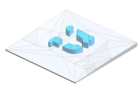
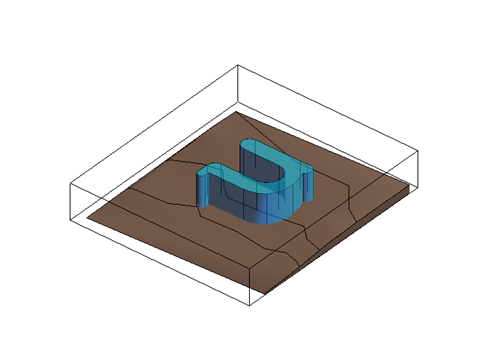
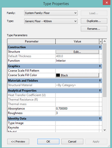
THE ARCHITECTURE OF 3D PRINTING A manual intended for public use with the scope of offering tips&tricks for the architecture community passionate about digital manufacturing. Printer used throughout this process is Ultimaker 3, however more than 90% of the examples can be done with and Ultimaker 2 as well, the main idea is the work-flow process. Software Packages used within this series: Autodesk Revit, Rhino, Grasshopper, STL exporter, Cura The goal of this exercises and blogs is to make custom profiles that can be used at a general scale for generic scenarios within the architecture community that is focused on 3D printing and expand the knowledge pool. Connect and have a relation with the Ultimaker Architecture contest about to launch, so you have a starting point. REVIT For the purpose of this experiment and journey, in order to not step on any toes, we will begin by making a custom house, on a random fantasy plot, so the conditions will be challenging and content specific. Also, for this experiment, the proposed design will be modeled as closely as possible to a real case scenario, so therefore some random issues you may encounter along your design and print process can be illustrated. 01. TOPOGRAPHY Topography is one of the most complicated issues in Revit to print out, mainly because unlike every other type of category and geometry within this software, it is not a solid, just a mesh. Project constrains: A plot, a plan outline – to make it more fun and challenging I chose the U from Ultimaker as a plan outline, programmatic wise, we will do a house/villa. Photo 1.1 - site plan view, the plot and the outline of the volume. Just to prove that a simple Revit topograpy can't be printed we will export an STL (see export chapter for more information) When the um-1 file is exported and imported into Cura, you can notice that the site has not been exported, and/or it was too thin to be recognized. However if the Revit export is done in mm and a section box is used: You can detect some presence of a topography, however nothing printable. To transform the topography there are two ways to go about it a. Use a script through dynamo, however this requires a particular skillset and can be quite a hassle. b. Second and most common choice is to re-do the topography from a floor. And in first instance it will look something like this (the highlighted straight floor contour) Next step, you would probably thicken the floor to 3-5 meters, depending on the scenario, for 2 reasons: a. You will add height points, so the thickness should be greater than the difference between your highest point and your lowest point, I have a height difference of 3 m in my example. b. The floor will offset when you add height points, and you will like to be able to have a flat base. That being said, you begin by selecting the floor and clicking Edit Type In this step you will edit the structure to thicken the floor: You don't need a lot of layers, just 1, with the proper thickness, in my case 5000 mm. Result: Cura visibility: As you can see the topography is flat, however it is printable and more importantly readable in Cura. The next step you are interested in is to get the right curves in your topography. Select the floor > Modify Tab > Add point The idea is to add a floor point for every elevation point you have in the topography and also to Modify sub elements in order to place them at the same level. Adding points: Modifying points: Compare the existing topography line with the top of the floor. Once you are satisfied with the result, select the topography and hide it in view. So the result will look something like this: However, before you are done, there is an extra step you need to take, and that is to level the bottom layer. To do that, you need to activate the section box, which is available in the Properties panel of any 3D view. With the section box than you can virtually cut and control the size of your future print. Remember this tool because it is very relevant in all the processes. In order to better control the section box cut, I would recommend setting it in a side view. The 3D result in Revit: The 3D result in cura: ONE OF THE 3D PRINTED RESULTS: UP NEXT : THE ARCHITECTURE OF 3D PRINTING - 02 MASSING alternativ 1.stl


-
@kmanstudios I do believe you since I see it happening live. But what procentage of the people at high end firms are able to do it as well? Personally I would like to know what software are you using in your day to day work for drawing production - because at the end of the day it all start there.
-
@Florisvh quality is a matter of opinion. So see photo and decide for yourself - that is unfortunately the only one I can share now. I have attached the Cura how to - in images as well, you have to select the Ultimaker material and automatically it will change the settings, than instead of custom you go to recommended and balance off the quality level from there. another tip - top/bottom thickness should be a multiple of layer height and wall thickness should be a multiple of nozzle.


-
@Florisvh since I don't know exactly what is going on with your printer or what type of model you are printing .... I am going to throw some tips your way and see if anything helps. I know it can be frustrating but you are not the only one going with through this. problem can occur due to 1. mechanical issues such as maintenance of the machine, it can be that the screw on on the extruder is too tight, that the hot end needs a cleaning or the bed is not clean and/or not calibrated. However my experience was so far that 99% of problems come from category no.2 the model and/or poor slicing. Here are my fail proof settings: Layer hight: 0.2 wall thickness: 1.2 top bottom thickness: 1.2 printspeed: 70 mm/s (I usually print at 100 but I have no patience in my blood) travel speed: 90 mm/s (120 mm/s - cause I have no patience) print temp. : 200 degrees (210 if you have aa 0.8 and 190 if you have aa 0.25 ) infill density: 5% which pattern though? However, since you are using UM material why not go for their standard already over-tested profiles ... and their standard settings - when in doubt - use the profiles! (if you are unclear where does are and how does work, drop a line and I will attach a screen grab)


