Jump to content

Recommended Posts

Posted · New UM, lots of problems.

Hi,

okay so I got my UM ready assembled but I am having many print problems with different settings. I am not running any crazy speeds just 50mm/s.

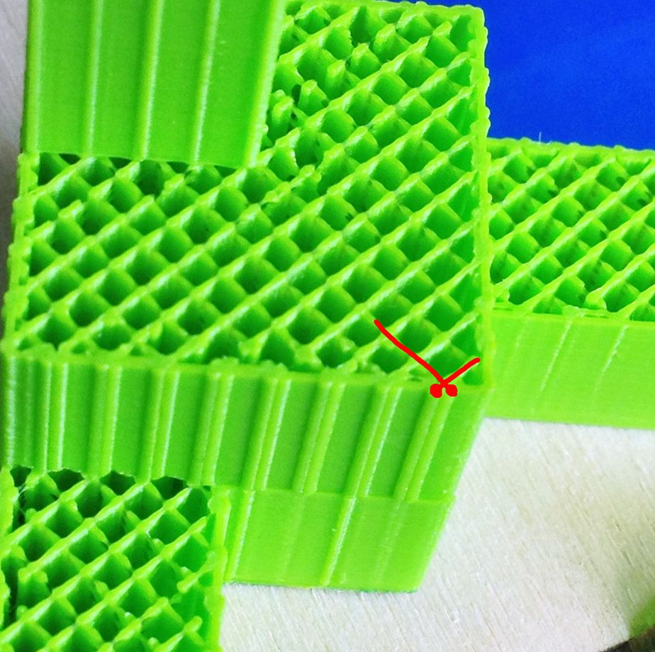
Here is the first problem printing a calibrating cube, you can notice all these vertical lines.

null_zpsf8ee8e9b.jpg

null_zpsf2b9e50b.jpg

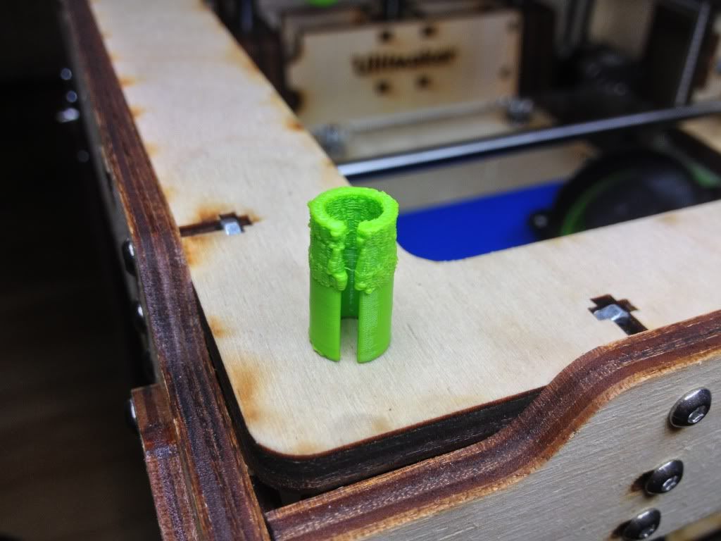
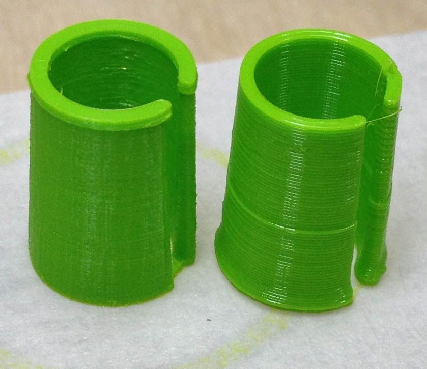
Now here is the other printing problem I am having.

null_zps15c4ea3c.jpg

null_zps8a55ed9c.jpg

seems like its too hot, I am running PLA at 230.

Any ideas would be appreciated.


  • Link to post
    Share on other sites

    Posted · New UM, lots of problems.

    you can normally print PLA at 190 to 200. try that and put on your fan full blast.... that should really help !!

    the tops of your models are getting too much heat.

    About the flow or lack of... try tightening the little spring on the back of your extruder, maybe the PLA is slipping a bit.

    Also feel the belts with your finger, if they are floppy, you need to print some belt tighteners and they should also help a lot.

    dont worry, it always takes a bit to get things really good !

    Ian :-)


  • Link to post
    Share on other sites

    Posted · New UM, lots of problems.

    Thanx lan,

    I did check all these things, my belts seems tight enough and no slipping but yes its probably too much heat on the top, but it prints fine for the bottom but than I get these issues at the top layers for some reason.

    I have reduced my temps to 200C for now and will see how it works out.

    What about the top picture with all these vertical lines ?


  • Link to post
    Share on other sites

    Posted · New UM, lots of problems.

    You should probably also guide the cooling air more towards your print with adjustable part on your fanduct, instead of straight down.

    Fanduct guidance

    As you can hopefully see on the picture, the fanduct is now guiding the air straight down.

    Try to bend this adjustable part more upwards, so that by eye the air would pass right under the nozzle.

    Lowering the temp to 200°C sounds like a good tip as well.

    Have you used a default profile with your cube, or did you start tweaking the settings in cura right away?

    Can you tell us some more about the settings you have used?


  • Link to post
    Share on other sites

    Posted · New UM, lots of problems.

    Sander,

    That's exactly why I am trying to print another fan duct, as the fan is not blowing under the hotend & therefore the extrusion doesn't cool down quickly.

    I still need to know what's happening with the 1st picture is it the Z-ball screw play that's causing these vertical lines ?


  • Link to post
    Share on other sites

    Posted · New UM, lots of problems.

    The vertical lines are clearly infill showing through. You can see this on the top view. There is a recent bug in cura (more here):

    http://umforum.ultimaker.com/index.php?/topic/2501-is-this-slicing-settings-or-hardware-problem/?p=17683

    This is easily fixed by doing 2 or 3 shell passes (set shell to .8 or 1.2) to keep the infill from coming outside the model. Alternatively you might have loose belts. Easier to tell if you provide an overhead view of the top layer of a cube printed. Also make sure "infill overlap" is at a reasonable value such as 15%.


  • Link to post
    Share on other sites

    Posted · New UM, lots of problems.

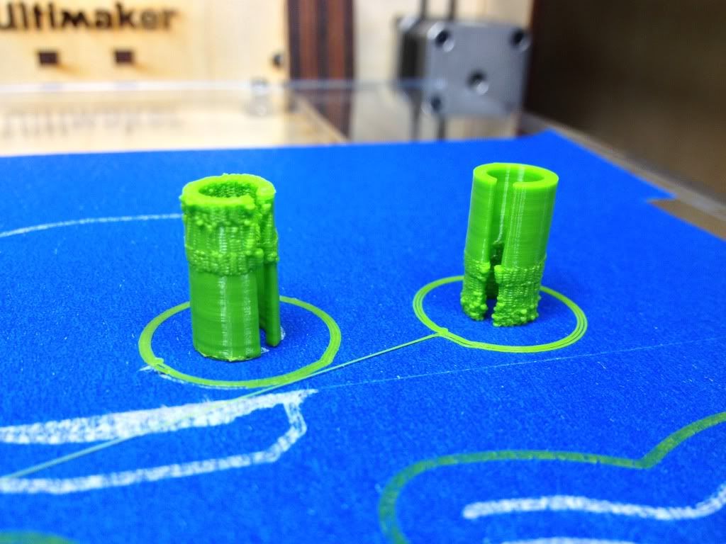
    The last photo with the 3 "cylinders" (are they all supposed to be cylindrical?)...

    I know it looks like a temperature issue but I'm pretty sure it is simple overextrusion (extruding too much). Most likely your z isn't moving as much as it should be - I think it is sticking or missing steps. You probably need to fix the z coupler. Look again at the photos of where the Z screw goes into the coupler and make sure you inserted it all the way. Also did you remember to put a drop of grease on the z screw? I would use cura or pronterface to move the Z axis 10mm at a time up and down and test it with a ruler taped to the ultimaker. You can place a pencil or something straight on the bed and make it touch the ruler so you can see pretty accurately. But with this much error we are talking at least 30% error (Z not moving far enough).


  • Link to post
    Share on other sites

    Posted · New UM, lots of problems.

    By the way I often print at 240C (depending on the part) and you should be able to print at that temp just fine if you don't care about stringing.


  • Link to post
    Share on other sites

    Posted · New UM, lots of problems.

    Oh - and I wouldn't print a new fan duct as the one the comes with the UM is really ideal. They tend to constrict air flow too much for the design of the current fan.


  • Link to post
    Share on other sites

    Posted · New UM, lots of problems.

    Oh - and I wouldn't print a new fan duct as the one the comes with the UM is really ideal. They tend to constrict air flow too much for the design of the current fan.


    But the original fan duct blows downs and not towards the layers laid by the extruder, so it doesn't cool them for the next layer !!?!?

    okay so you are correct about these vertical lines, here is a top picture view.

    I drew two red lines to indicate the infills.

    IMG_2525_zps449ac7bd.jpg

    The only other problem I am still having and something tells me it might be the part itself is the sagging in these pictures.

    so what I did is print these cylindrical shape twice using 198C and still the issue at the top, so I went ahead & flipped the part 180 degree and printed it again & the problem is now at the bottom, so I'm not sure if its an over extrusion issue, I have my flow set @ 100% and everything else prints fine, maybe I need to measure my actual filament(just did using calibers), so instead of using 2.89 its actually 2.94 but can that cause this problem.

    null_zps4f7eb509.jpg

    here it is printer upside down, can it be the actual model that has a problem ?

    null_zpsbd5b858d.jpg


  • Link to post
    Share on other sites

    Posted · New UM, lots of problems.

    this is the cone I am trying to print if someone wants to give it a try and see if they are getting the same issue, only the cone, the rest printed fine.

    http://www.thingiverse.com/thing:17027


  • Link to post
    Share on other sites

    Posted · New UM, lots of problems.

    Something is weird in the slicing. I'm going to guess the upper and lower walls of the cylinder are a different width. Look at it carefully in Cura in slice view and also in your CAD.

    Some slicing bug. What is your:

    nozzle width

    shell thickness

    infill percent

    And about how thick is that wall in cad? How thick at the top and how thick at the bottom?

    You might want to do shell thickness=4mm and turn off infill. See if that looks better in Cura.


  • Link to post
    Share on other sites

    Posted · New UM, lots of problems.

    I'd say It's the thin end of the cone giving the problem. You need to have the fan on and increase the minimum layer time setting in Cura. It is putting the next layer down before the previous layer has cooled down. Sorry I haven't read the rest of this post.


  • Link to post
    Share on other sites

    Posted · New UM, lots of problems.

    Nozzle is 0.4mm

    infill is 50%

    Top & Bottom are set same as layer size which is 0.15 for the last two cones.

    i do have the fan at full blast, if you guys have the time try printing that part is a small part, only the cone please.

    Also i don't understand why i need to increase layer time since it prints fine for the bottom part but i will give it a try, currently set @ 5 if i remember correctly.


  • Link to post
    Share on other sites

    Posted · New UM, lots of problems.

    Did you watch it print? Does it really take 5 seconds per layer as that is very important. There is a "minimum extrusion rate" or something like that (or there used to be) which should really be set to 0 as this can override the 5 second rule.

    Owen could be right as it looks similar to the cooling issue but I still think it's a slicing issue and if you look at the gcode carefully you should be able to see the problem. I think it's over extruding - putting too much infill in there somewhere. Cura has lots of minor bugs that show up in things like this - maybe there is still a "thin wall" bug.


  • Link to post
    Share on other sites

    Posted · New UM, lots of problems.

    So I printed out the normal cone and it printed almost fine (the almost is that three times cura puts a tool path across the opening - so there are three strings - but they are fairly easy to get rid of - otherwise looks lovely.

    So there is something funny in the slicing, but not so bad as you are showing in yours - just to check though I printed the normal cone, not the very tight one.

    James


  • Link to post
    Share on other sites

    Posted · New UM, lots of problems.

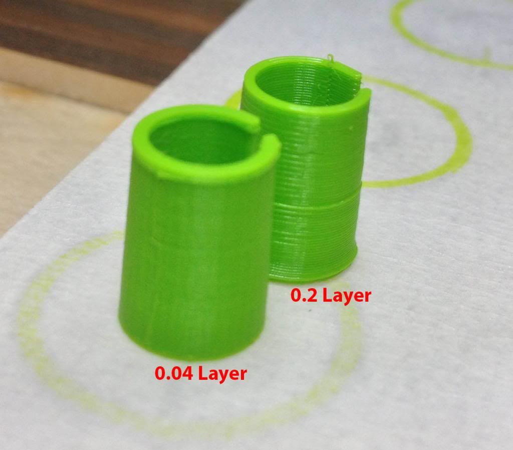
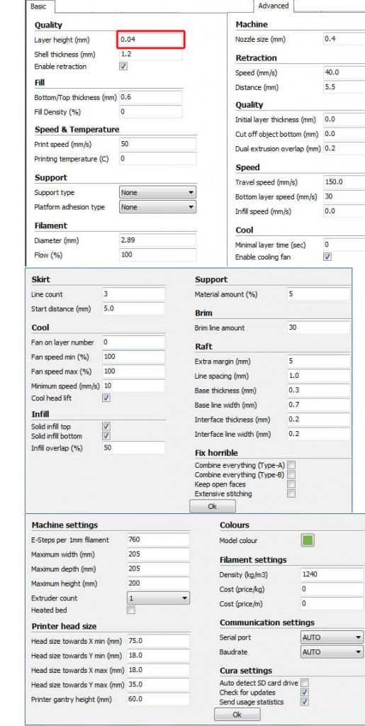
    Okay, got things working now, here is 0.2 vs 0.04 layer height :) looks very good, also attached settings incase anyone is interested.

    layer004_zpse6d86515.jpg

    IMG_2536_zps1de4697a.jpg

    4micron_zps76e2070e.jpg


  • Link to post
    Share on other sites

    Posted · New UM, lots of problems.

    looks very nice now :-)


  • Link to post
    Share on other sites

    Posted · New UM, lots of problems.

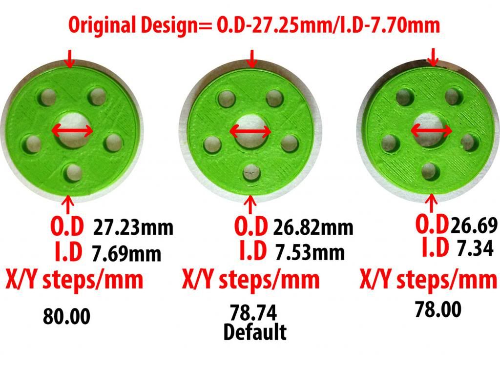
    Okay, so I was designing a part in solidworks for my Steyr Hunting 5 and after measuring the actual print it seems its a bit off and I needed to correct that other wise I will have issues, so I played a bit with the X & Y steps/mm & here is what I came up with.

    The original part had an O.D (Outer Diameter of -27.25mm) (Inner Diameter of -7.7mm). Hope this helps some new users.

    e-steps-mm_zpsa340bb3f.jpg


  • Link to post
    Share on other sites

    Posted · New UM, lots of problems.

    I strongly advise you not to mess with steps/mm as they are probably fine.

    The problem is that PLA shrinks when it cools (among other issues such that you might have only had 10 or 20 segments in your outer circle which also reduces the diameter).

    Much better to increase your CAD model outer diameter by 1.6% (80/78.74) or scale your object by 1.6% in Cura.

    You will have different scaling needs at different scales. So a part that is 100mm long will need much less correction than a part 10mm long. So "fixing" this with steps/mm will only work for parts that are about 27mm across and are cylinders. Other shapes might need slightly different scaling.


    Thank you gr5 & I appreciate your help & feedback but I will have to disagree with you here.

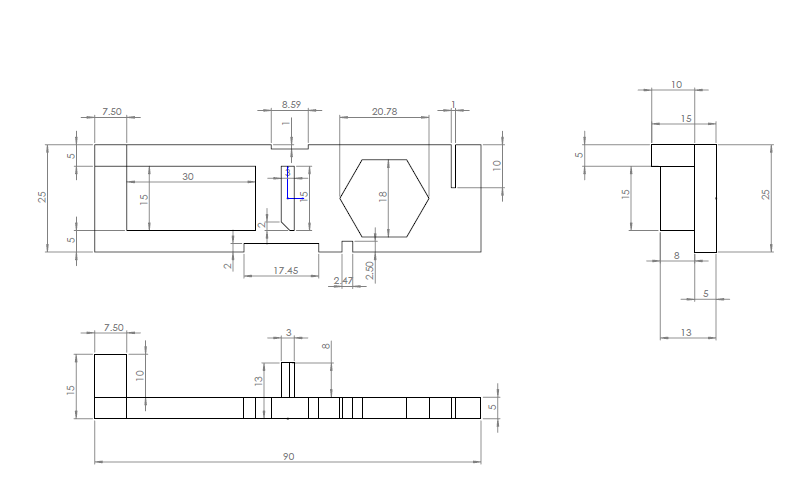
    Cause X/Y steps will obviously effect all X & Y and hence cylinders, squares & any other shapes & in fact I have already drawn a design in solidworks as can been seen below to check these & after measurement its much closer to the actual dimensions.

    I did measure all sizes for the below print but I didn't write them down.

    123_zps5c935bc7.png

    null_zpsa60fc9f7.jpg


  • Link to post
    Share on other sites

    Posted · New UM, lots of problems.

    I think George's point was that the steps per mm for x and Y is a mechanical function of the size of the pulleys and the stepping of the motors, and nothing else. As such, the default values are probably the 'correct' ones for the Ultimaker hardware.

    However, many other things affect the size of finished parts, including positioning inaccuracy due to backlash, and the cooling and shrinkage of the plastic, as well as the fact that the slicing process approximates curved surfaces with straight line segments, and so can further distort dimensions - especially of small holes. The factors all behave differently for different models, leading to different results.

    Tuning the steps per mm to counteract these factors for one model is going to give different results with different models. Or even with the same model oriented differently on the build plate, or printed with different materials, or at different speeds and temperatures.

    As such, you'll probably get more predictable results overall by understanding how your materials behave for the types of object that you print, and then adjusting the model accordingly, rather than trying to find a magic 'steps per mm' value at which everything will be right.


  • Link to post
    Share on other sites

    Posted · New UM, lots of problems.

    I agree, but in my case when I am designing a part than I have to take the measurements that work with many things & fits right & its a pain to alter these to get it to print well & than alter them again if I am sending them for CNC machining.

    Obviously the tweaks I am doing are only good for my printer but isn't that the whole point ? Ultimaker makes their printers to work for the general public but each one can fine tune his/her printer to work best for his/her job & that's what I am trying to do.

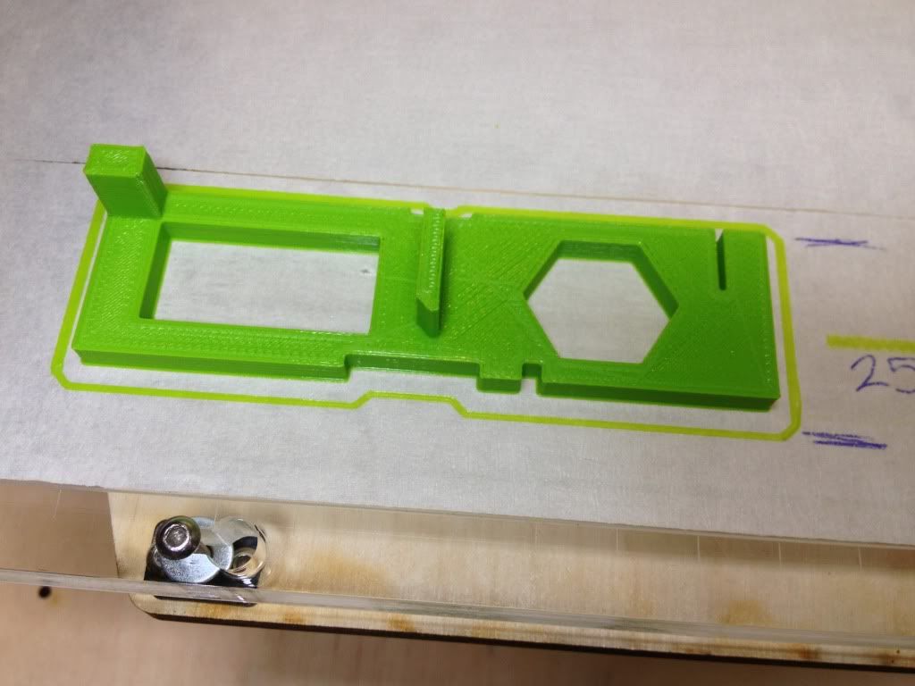
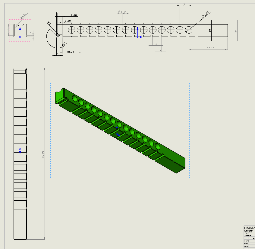
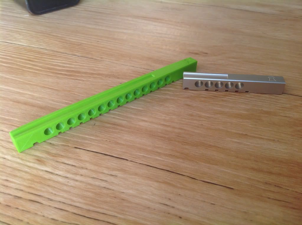
    This is a Magazine I just did that will be sent for CNC and the pellets has to fit just snug where they don't fall off nor do they get dent & shoot not straight & also the whole things has to be cycle well and there fore the tolerances has to be very tight, it would be a pain to change each & every dimension to print right & than re change them to send for CNC, and there is always a chance I forget to change a particular dimension.

    I would rather change my printer settings to get it as close as possible to my design & not the other way round.

    Its a given that PLA shrinks and many other factors but that's besides the initial point.

    steyr14shotmagazinedawing_zps31c25be0.png

    9e377a296b8ca37cc4a47ae66b997dc5_zps453f6066.jpg


  • Link to post
    Share on other sites

    Posted · New UM, lots of problems.

    Well, yes, But the point was just that the amount by which you change the steps is probably going to need be different depending on the object that you're printing, and, in practice, the amount of change that you need is probably going to be different in different areas of the same print (e.g., for holes, compared to straight parts).

    Changing the steps is one way to adjust on a crude level, but all that does is to effectively change the overall scale of the object anyway. Wouldn't it be easier in that case, to just scale the object up and down directly in the slicer, rather than the slightly more fiddly process of adjusting the steps setting in the firmware?


  • Link to post
    Share on other sites

    Posted · New UM, lots of problems.

    Maybe you are right, naz72. Maybe this 1.6% scaling is enough of a correction to get 90% of the errors. I'm starting to think maybe it's a good idea as a first approximation of correcting values. I'm not convinced that it will work for larger parts over 100mm in two dimensions. Maybe after you have printed some larger parts you can let us know how those outside dimensions went - exactly how accurate they were. I suspect you will need to undo some of that 1.6% but I could be wrong.

    What I think happens when printing a square is that as the nozzle lays down the outer edge, after it converts to a solid it shrinks, then when the nozzle comes by later for the next pass the nozzle is farther outside of the print and lays the next layer outside the layer below by a little bit. Then that shrinks. This keeps repeating and is why it is easy to see the layers even at .1mm height.

    So the printer keeps trying to correct for the shrinkage and this explains why larger parts don't need as much correction. Or maybe I'm wrong. Maybe larger parts need less correction because they take longer to do a layer so the part cools more completely before the next layer is placed down.


  • Link to post
    Share on other sites

    Create an account or sign in to comment

    You need to be a member in order to leave a comment

    Create an account

    Sign up for a new account in our community. It's easy!

    Register a new account

    Sign in

    Already have an account? Sign in here.

    Sign In Now
    • Our picks

      • UltiMaker Cura 5.9 stable released!
        Here comes Cura 5.9 and in this stable release we have lots of material and printer profiles for UltiMaker printers, including the newly released Sketch Sprint. Additionally, scarf seams have been introduced alongside even more print settings and improvements.  Check out the rest of this article to find out the details on all of that and more
          • Like
        • 5 replies
      • Introducing the UltiMaker Factor 4
        We are happy to announce the next evolution in the UltiMaker 3D printer lineup: the UltiMaker Factor 4 industrial-grade 3D printer, designed to take manufacturing to new levels of efficiency and reliability. Factor 4 is an end-to-end 3D printing solution for light industrial applications
          • Heart
          • Thanks
          • Like
        • 4 replies
    ×
    ×
    • Create New...