Jump to content

Conversion Ultimaker 2 Extended to Dual Extruder and Continuous Fiber Printing


Recommended Posts

Posted · Conversion Ultimaker 2 Extended to Dual Extruder and Continuous Fiber Printing

Hello dear community,


as part of a project I would like to convert my Ultimaker 2 Extended to dual extruder. The second nozzle should print continuous carbon fiber. The cutting tool for cutting the fiber and the matching slicer (Aura) is already ready. The carbon fiber and the base material (PA6) are also ready. The conversion to dual extruder will be done according to the instructions. To keep the original motherboard, I would like to control the slicing tool (MG90S motor with return spring) via a free output for additional fans (24V). The question is, is this possible and which GCode command do I need for this. I would be happy if someone has some advice. Thanks a lot.


Greetings 


Patrick


  • Link to post
    Share on other sites

    Posted · Conversion Ultimaker 2 Extended to Dual Extruder and Continuous Fiber Printing

    @tinkergnome - are there gcodes that can set the percent for another fan like output?  And what pins might be available on the UM2?


    @PatrickTri - I doubt any extra pins will be able to control 24V - I think they will be 5V. 


    On the other hand, most UM2 printers have an extra stepper driver (you'd have to look at your board - you have to remove the 4 screws holding it in and turn it over I think to see - but there is a large, obvious, square chip roughly lined up with each connector that goes to the servos.  Some newer UM2 series printers don't have a chip for the second extruder but many do.


  • Link to post
    Share on other sites

    Posted · Conversion Ultimaker 2 Extended to Dual Extruder and Continuous Fiber Printing
    9 hours ago, gr5 said:

    are there gcodes that can set the percent for another fan like output?  And what pins might be available on the UM2?


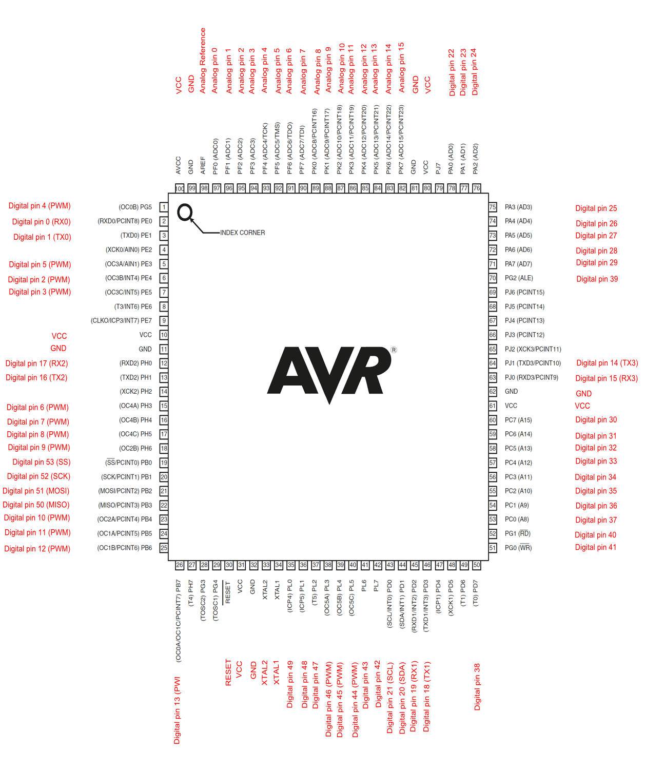
    @PatrickTri - in case you don't know it yet - schematics are available here:

    https://github.com/Ultimaker/Ultimaker2/tree/master/1091_Main_board_v2.1.1_(x1)


    The question is - how much current is needed?

    The "LED PWM" output is 24V - that's perhaps an option if the lights are not needed... and if it can handle the current?

    Thats important - don't guess unless you're experienced in repairing smd components...


    How does this slicing tool work?

    There are some other Arduino pins available on the mainboard that can be used as an on/off trigger. But as @gr5 said - this would need some kind of amplifier board (relay / mosfet - whatever...) - maybe such a thing is already integrated in the tool?


    Marlin firmware can set pin states with gcode M42. I think this alone will not fit the purpose, but who knows?


    14 hours ago, PatrickTri said:

    The conversion to dual extruder will be done according to the instructions.


    BTW: which conversion instructions are you referring to?


  • Link to post
    Share on other sites

    Posted · Conversion Ultimaker 2 Extended to Dual Extruder and Continuous Fiber Printing

    M42!  That's it.  Nice.  You can turn the pin off, or you can set the pin high or low or you can sit it to pulse at a duty cycle from 0 (0%) to 255 (100% on).  The schematic can help you find a spare pin - some go to header connectors similar to on an arduino - so those are easy to get access to with a simple female connector.  Ground is usually available nearby.


  • Link to post
    Share on other sites

    Posted (edited) · Conversion Ultimaker 2 Extended to Dual Extruder and Continuous Fiber Printing

    Thank you very much for your answers @gr5 and @tinkergnome. In the attachment you will find the installed board. A connection for a second extruder is available, as far as I can see. 


    The motor of the cutting tool has an integrated PWM control. The supply voltage is 6 V. So I could do it without a MOSFET right ?


    The question is: Which free connector on the board can I control with a specific GCode command and how can I select the connector? What would the command have to be to select a pin directly. 


    If you would recommend a pin on the board, I would be very grateful. 


    With the slicer software Aura I have generated a GCode for a fiber reinforced component. Looking at the GCode, I noticed that a separate command is used for the moment the fiber is cut. This command is for the printers of the company of Aura.


    The target is:
    1. select free pin on the board of the UM2.
    2. command to select this pin
    3. replace specific command in GCode of Aura with the new command.


    If I forgot something, please let me know. 

    I am very grateful for your help and your quick answers. 


    Many greetings 


    Patrick


    Board UM2E.jpg

    MG90S_Tower-Pro.pdf

    Edited by PatrickTri
    Missing Part
  • Link to post
    Share on other sites

    Posted (edited) · Conversion Ultimaker 2 Extended to Dual Extruder and Continuous Fiber Printing
    22 hours ago, PatrickTri said:

    In the attachment you will find the installed board.


    OK, it needs VCC, Ground and a PWM-capable control pin with 5V logic.

    The challenge is to modify the firmware for a 50Hz PWM frequency on a specific pin. If it is even possible - i dunno?


    image.png.544ec2da974ec3c655b181c0777ff627.png


    PWM frequency aside:

    You'll find all three outputs side by side on header J26 (EXP3)  (there are others - it's just a possibility i choose)


    image.thumb.png.6f18b394136f9fa2e855d85620470a12.png


    image.png.915be47d0c073e2e012747c79ba9f9a0.png


    Marlin firmware uses digital pin numbers, so PB7 translates to pin 13.

    That means the gcode looks like this (range for parameter S is 0..255 and would set the servo angle):


    M42 P13 S128


    Marlin gcode documentation - but keep in mind that Ultimaker firmware is based on the old Marlin 1.0

    https://marlinfw.org/docs/gcode/M042.html


    Arduino pin mapping:

    https://docs.arduino.cc/static/ed4d33b86bac66d54959fbb186795a11/54c3a/PinMap2560big_Rev2.png


    Good luck!


    Edit (regarding the duty cycle and frequency problem):

    There is builtin support for servos in Marlin. It's not enabled by default, you have to configure (and compile) it.

    https://marlinfw.org/docs/configuration/configuration.html#servos


    gcode M280 is meant to be used for servos:

    https://marlinfw.org/docs/gcode/M280.html


    M280 does not use pin numbers but the servo index instead- starting with index zero...

    ...so - don't forget to set the correct pin number for "SERVO0_PIN" in pins.h


    I never used such things by myself - i'm sure you're able to figure out how this works!


    Edited by tinkergnome
  • Link to post
    Share on other sites

    Posted · Conversion Ultimaker 2 Extended to Dual Extruder and Continuous Fiber Printing
    On 4/1/2022 at 11:39 AM, PatrickTri said:

    Looking at the GCode, I noticed that a separate command is used for the moment the fiber is cut.

    Which gcode?  Is it M280?


    And for help building marlin (or I recommend tinkerMarlin) there are instructions here:

    https://community.ultimaker.com/topic/16856-how-to-build-marlin-the-way-tinkerghome-and-ultimaker-do-it-if-you-have-windows/


  • Link to post
    Share on other sites

    Posted · Conversion Ultimaker 2 Extended to Dual Extruder and Continuous Fiber Printing

    Thank you very much for your active support @gr5 and @tinkergnome. I am very grateful for it. I have looked at the GCode and when cutting the fiber, the following GCode is displayed/used.


    M400
    M280 P0 S30
    G4 P200
    M280 P0 S90
    M400


    So the command is M280 as you have already described. 


    At the moment I am designing the framework for the cutting tool. As soon as the ordered motor arrives I will work on the software to do the first test via Pronterface. Of course I will do the test in a disassembled state to ensure a proper control. If you have further tips please let me know. Thanks again for your support. I will give you some updates later 🙂


    Best regards


    Patrick 


  • Link to post
    Share on other sites

    Posted · Conversion Ultimaker 2 Extended to Dual Extruder and Continuous Fiber Printing

    Hey, 


    at the moment I am busy with the assembly of the second nozzle. In many threads I have read that an installation of a second nozzle for the UM2 Extended from Ultimaker was discarded as an idea. According to threads, there should be problems with heat transfer between the nozzles and also collision risk when printing. As a dual extruder conversion I have seen the Mark 2 and the DXU conversion. Which one would you recommend and do you know where the parts are available. Unfortunately, most of the links of the purchased parts for this are no longer current or the parts are no longer available. Do you know of any other rebuilds or ways to build a dual extruder

    @gr5 and @tinkergnome? I would be glad about an answer. 


    Greetings


    Patrick


  • Link to post
    Share on other sites

    Posted · Conversion Ultimaker 2 Extended to Dual Extruder and Continuous Fiber Printing

    I thought you were going to do continuous fiber?  What does that have to do with a second nozzle?  Now I'm confused.  


    I think that adding a second extruder is a big project.  Adding a continuous fiber is also quite a big project.  Why do both at the same time?


    Anyway if you are doing just normal filament then you don't need the M280. 


    I would trust the mark2 because I know a few people who did it and it works very well but the kit no longer seems to be available.  You can get most of the parts on aliexpress and you don't need the circuit board (just solder the proper cables together).  But you do need quite a few parts.  I think you can get them all on aliexpress.


    The DXU option seems quite good as well.


    Still don't see what this has to do with continuous fiber?


  • Link to post
    Share on other sites

    Posted · Conversion Ultimaker 2 Extended to Dual Extruder and Continuous Fiber Printing

    Hey,


    thanks a lot for your answer @gr5. Sorry for the confusion 😄


    I need a second nozzle because the printing process is roughly as follows.
    1. printing the base material with one nozzle. 
    2. second nozzle with continuous fiber prints to the specific areas that need to be reinforced. (With the Slicer Aura you can place the fiber specifically)
    3. just before the fiber is finished in one layer, the fiber is cut. (Command M280 is used here)


    The fiber itself is not printed because the melting temperature is much too high. The base material is PA6 and the continuous fiber is coated with PA6. So the fiber coating is melted and bonded to the base material. 


    Therefore, I need a dual extruder. Since the UM2 was never officially launched as a dual extruder, I need an alternative. That's when I saw the Mark2. Here I would use the second extruder for the base material and the main extruder for the additional material (continuous filament), because here the cutting tool must be placed on the head. 


    Unfortunately the board is no longer available on Aliexpress 😕


    If you have any other tips, feel free to let me know 🙂


    Greetings from Bavaria (Germany)


    Patrick


  • Link to post
    Share on other sites

    Posted · Conversion Ultimaker 2 Extended to Dual Extruder and Continuous Fiber Printing

    Well most of the parts are available on aliexpress if you search for things like "ultimaker 2 printhead"  for the head and "ultimaker 2 feeder".  For the stepper motor go to this link and click "contact" and tell them you just want the extruder stepper motor (the bigger one without the z screw):

    https://www.aliexpress.com/item/32796683178.html


    But first, what is the diameter of this nylon (PA6) filament?  Is it 2.85mm?  Or is it 1.75mm?  If 1.75mm then you need a 1.75mm solution.  You can get a 3mm to 1.75mm conversion kit from 3dsolex.


  • Link to post
    Share on other sites

    Posted (edited) · Conversion Ultimaker 2 Extended to Dual Extruder and Continuous Fiber Printing
    1 hour ago, gr5 said:

    Well most of the parts are available on aliexpress if you search for things like "ultimaker 2 printhead"  for the head and "ultimaker 2 feeder".  For the stepper motor go to this link and click "contact" and tell them you just want the extruder stepper motor (the bigger one without the z screw):

    https://www.aliexpress.com/item/32796683178.html

    I got most of the parts. The Mark2 Board isn't available anymore but i will solder the wires instead. 


    1 hour ago, gr5 said:

    But first, what is the diameter of this nylon (PA6) filament?  Is it 2.85mm?  Or is it 1.75mm?  If 1.75mm then you need a 1.75mm solution.  You can get a 3mm to 1.75mm conversion kit from 3dsolex.

    Both filaments are 2,85mm 🙂 


    Edited by PatrickTri
    • Like 1
    Link to post
    Share on other sites

    Posted · Conversion Ultimaker 2 Extended to Dual Extruder and Continuous Fiber Printing

    So an update after some time: 

    • I decided to go with the Mark2 solution and printed and installed all the parts. 
    • The filament PA6 has a diameter of 1.75mm and the nozzle head and all parts accordingly converted to 1.75mm. 
    • The continuous filament has a diameter of 0.4mm. For this I have converted an aluminum extruder and milled a corresponding groove in a ball bearing so that the filament is guided correctly. 
    • The framework for the cutting tool is also ready and built. 

    I was not informed about the change in filament diameter, so the first information was that both filaments are 3mm. 


    Now I'm on the adjustment of the firmware and there came some problems. After some messages with @tinkergnome (Here again many thanks for all your tips and help 🙂 ) I am so far that I can adjust the firmware with Arduino IDE. Unfortunately the following problem has settled. No matter if I adjust a pinout in the original source code of the UM2 Extendend or in the Mark2 firmware, no traverse of the axes or the print bed can be done. As soon as I start a traverse, the printer becomes very noisy and it sounds as if the motors are all blocking. Installing the original Mark2 firmware works fine with all features. But as soon as I make an adjustment it no longer works. As soon as the pin is deposited and the servo function is activated in Config.h, the servo motor can be controlled via Pronterface (command M280 P0 S30) but no movement of the axes or the print head can be performed and the servo motor twitches at standstill.


    Example: in Pins.h store #define Servo0_PIN 13 and upload again via the Arduino IDE.


    Does anyone have an idea ? 😄


  • Link to post
    Share on other sites

    Posted (edited) · Conversion Ultimaker 2 Extended to Dual Extruder and Continuous Fiber Printing

    Another Update:


    So something weird is happening 😄 


    I stored in Pins.h #define Servo0_PIN 13 in the Mark 2 firmware with Arduino IDE and now it's working. I can change the tool head and all the other features. 


    BUT 😄 


    I can't reach the Servo with the command M280 P0 S30 or other angles. Instead it's working with M42 P13. Even if in config.h the Num servos is set to 1. 


    Maybe i am missing something ? 


    Edited by PatrickTri
  • Link to post
    Share on other sites

    Posted · Conversion Ultimaker 2 Extended to Dual Extruder and Continuous Fiber Printing

    I can't help with the board and commands.


    But I have one suggestion: if you are going to add extra motors and stuff, consider feeding all of them from a separate power-supply, all with their own power-transistors. And switch these power-transistors (or MOSFETS or whatever) on and off via opto-couplers. Then you have no electrical connections between the add-ons and the original main board, and thus the least risk of overloading or short-circuiting that board, or the original power-supply. Motors can give nasty spikes and oscillations that could easily destroy the main board, even with diodes.


  • Link to post
    Share on other sites

    Create an account or sign in to comment

    You need to be a member in order to leave a comment

    Create an account

    Sign up for a new account in our community. It's easy!

    Register a new account

    Sign in

    Already have an account? Sign in here.

    Sign In Now
    • Our picks

      • Introducing Universal Cura Projects in the UltiMaker Cura 5.7 beta
        Strap in for the first Cura release of 2024! This 5.7 beta release brings new material profiles as well as cloud printing for Method series printers, and introduces a powerful new way of sharing print settings using printer-agnostic project files! Also, if you want to download the cute dinosaur card holder featured below, it was specially designed for this release and can be found on Thingiverse! 
          • Like
        • 10 replies
      • S-Line Firmware 8.3.0 was released Nov. 20th on the "Latest" firmware branch.
        (Sorry, was out of office when this released)

        This update is for...
        All UltiMaker S series  
        New features
         
        Temperature status. During print preparation, the temperatures of the print cores and build plate will be shown on the display. This gives a better indication of the progress and remaining wait time. Save log files in paused state. It is now possible to save the printer's log files to USB if the currently active print job is paused. Previously, the Dump logs to USB option was only enabled if the printer was in idle state. Confirm print removal via Digital Factory. If the printer is connected to the Digital Factory, it is now possible to confirm the removal of a previous print job via the Digital Factory interface. This is useful in situations where the build plate is clear, but the operator forgot to select Confirm removal on the printer’s display. Visit this page for more information about this feature.
          • Like
        • 0 replies
    ×
    ×
    • Create New...