

DidierKlein 729
Hi,
Not sure if i understand it's better with pictures 
It's probably due to the heated bed temp? What settings to you use? And what's the material?

Hi,
Not sure if i understand it's better with pictures
It's probably due to the heated bed temp? What settings to you use? And what's the material?
The print I made some 1.5 years ago was
* PLA
* no heated bed
(and I have that in front of me).
The print I made a few days ago (and my friend's)
* ABS
* heated bed at 100deg. WITH capton on the bed.
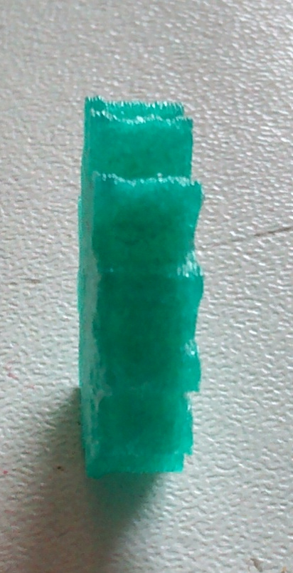
This is the PLA thing that I now have access to:
The effect is more pronounced with the ABS.
Wow - that's kind of crappy looking. Is it possible you were messing with the fan towards the end of the print?
Both PLA and ABS have similar linear graphs if you plot density versus temperature. It's pretty linear right through the glass and melting temps. And both have about the same slope. But ABS has a much higher glass temp (it's solid up until around 90C wherease PLA gets soft around 50C). Both have similar melt temps (180-210).
When the filament (both PLA and ABS) comes out of the nozzle it hits cold air (even if air is at 100C) and starts to shrink immediately and is basically like a liquid rubber band. Like nasal discharge. So when it makes those teeth there is a small but non-zero force pulling the teeth towards the center of the gear. With PLA this force is more extreme while it is still in the liquid phase because it has more to cool before it hits glass temp. With ABS it is more extreme in the solid phase and you are more likely to get a different problem - parts lifting off the bed. Because it has a longer temperature differential (90C to 20C) in the solid phase.
This "rubber band" effect is probably your biggest effect - it affects the tips of the gear teeth the most. For more rounded parts there are different cooling issues. But with pointy corners the rubber band effect makes the points shorter.
For PLA if the bed is at 75C (too hot) you get this pulling effect strongest down at the heated bed because the PLA never gets below glass temp so it is soft (like clay or even peanut butter) and the edges are pulled in a little more on each succeeding layer. But as you get away from the bed it starts to go back out because the layer below is more solid and holds the still-wet layer in place.
The bottom most layer sticks out more than other layers probably because your leveling was off by the tiniest bit and it got squished a bit. Also it was placed in the correct spot but the layers above got pulled inward.
So what's the fix? For PLA you want 100% fan and you want it soon - by 1mm that fan needs to be at 100%. Also printing slow might help if your layers are less than 5 seconds per layer. But most importantly keep the bed cooler - 50C is plenty on a glass bed to get the PLA to stick well. Especially if you use a thin layer of glue also.
For ABS I'm much less experienced. I assume that having the bed at 90C instead of 100C might help but I don't know. For me, having 0% fan with ABS works best for me. So I'm not sure what to do for ABS. Most experts seem to enclose the entire printer to keep the part at 90C or so.
Also in general printing slower helps. I can get much much better quality than you got on my UM Original or UM2 at 70mm/sec but the quality gets even better at 35mm/sec and even better at 20mm/sec. I've never tried slower than 20mm/sec because, well, the quality is stunning. I don't think it can get better.
(i.e. on a small base, growing slightly bigger upwards).
This is THE most challenging kind of print. In my opinion. The cause is *also* the rubber band effect. The only effective solution I know is to use more fan. Although I keep meaning to experiment with layer heights. Oh - also printing at 5mm/sec (wow slow!) and 2 passes on the shell help. More details here:
http://umforum.ultimaker.com/index.php?/topic/4094-raised-edges/
I've been thinking about this some more.
One of the problems of 3D-printing with extruded plastic is making the object stick to the platform. If you just extrude a strand of plastic it will just "lie there" on the platform, and it won't provide a base for the rest of the print.
So probably to make it stick, I have a tendency to configure the software/hardware to provide say plastic for a 0.2mm first layer, while the hardware has only 0.15mm clearance between the head and the platform. This creates some extra pressure and makes the object stick better.
But the "extra material" has to go somewhere. So for a few layers there is an over-extrusion that causes the bulge.
But providing "just enough" plastic for the first layer makes it stick less... What to do?
While, for resolution purposes you normally like to use settings like: "I Have a 0.4mm nozzle, so lay down lines of 0.4mm", for the first layer if you change that to: "Please lay down a 0.8mm line", you will extrude enough plastic for a 0.8mm line, which is extruded through the 0.4mm nozzle, pushes against the platform and the flat part of the nozzle before being left alone to solidify.
I don't have dayly access to the 3D printer (I have friends with printers, but not one of my own). To test this without having to modify the slicer, I'd slice a print at "my nozzle is 0.8mm" and at 0.4, and the splice together the start of the 0.8 gcode-file with the rest of the 0.4 file after the first layer. Anyone game to try it? (in case you're not into messing with gcode files: you do the slicing, I do the splicing: send me the files)
@gr5: the macro-foto brings out the "worst", besides the bulge at the bottom, it looks reasonable in real life.
Your observation is correct.
The leveling is the most important factor of this issue.
For very good results the best solution is to add a bevel/chamfer to all your bottom edges. (the bottom face).
A chamfer with the size of the "initial layer" OR "initial layer" + "layer hight" seems a good value.
You're saying to make my bottom face one line-size smaller. So both the first and second layer get to move into the leftover spot. Ok. That's another option. (but if I'm over-extruding, that might be causing problems on the inside somewhere as well.).
The thing is: For a one-off project, just modifying the object is simplest and fastest. And it works to test out a theory like yours. But in the long run, I think we should define the models to be "the way we want the resulting object to be", and that the tool-chain is able to adjust for the inaccuracies of the building process. Suppose I build a few prototypes on my home-3D printer, and then go to order it at shapeways on their fused-nylon process. If I've made a bunch of adjustments in the model for my home 3D printer, then I'd have to undo those again before sending it off to shapeways. This is bound to go wrong at some point. We should work towards the tool-chain helping us getting as close as possible to the model.
If you adjust the model for the printing process, you're going to be adjusting everything again the moment you move to another printer. (e.g.: I have two friends with a 3D printer where I can print things if I want to. Different brands....).
I think that any "tool chain" should always be thought to also include a "design tool". Not the one used to primarily design a model, but a functional component (of the chain) that would be able to provide the "adaptation" to the specific production technology.
Now, if adaptation is automatic, e.g. embedded into the host and/or firmware, or manual, e.g. you have to open the model in a 3D modelling program and alter it, this is another story. It would be nice to have it automatic
On the other hand there is the "finishing" component of the process, as well. For example, even injection molding requires post-processing. Once again, if this is achieved automatic or manual, is another story. So to say, you can file the bottom edges of a 3D printed part and admit that filing is a manual form of post-processing.
It might be that one day a particular production technology will be fully agnostic of the model design (or the other way around). But for the time being is not. Not even for the industry-standard injection molding (just for a quick lecture) which we always like to compare the printed parts to.
Yes, some production processes require manual or non-manual postprocessing.
But the idea of a 3D printer is that I can make stuff that I wouldn't otherwise be able to. One of the things I want to be able to make is "gears". The "gear train" of commercial products are usually injection molded nylon. But there are so many different sizes and shapes that it is not possible to just have a few in stock and build something useful out of it. Lego and Fisher-technik come a long way to solving this.
Anyway, if I print a gear and it has a base that is wider than the rest, it will not allow me to put the gears close enough to the other gear to have the teeth mesh over the full height. When there is just one gear meshing with another gear, you can turn one around and have the extra "rim" fall outside the other gear. So this way you can have about 80% of the gears meshing with the other one. But that won't always be possible.
Anyway... We levelled the bed again, lowered it a bit. That helped. We lost about 50% of the "bulge" at the bottom. The gear went from 11.6mm at the base to 11.1 mm at the base, with a 10.6mm measurement at the "flat" part.
We lowered the bed-temperature to 90 degrees (from 100). A print we tried then (with a big base of about 100x35mm) simply didn't stick. It came off after two layers. We increased the temp back to 100, and finished the print. -> 90 is too low, 100 is about right. (I'm not sure how accurate those numbers are in an absolute sense....)
My suggestion to lay down the first layer with a wider line-width has already been implemented in cura. I was going to splice together the gear with a different line-width setting when I noticed that the first layer didn't change.
The weird thing is that although the setting was "1mm", it seems to have a 0.8mm pitch in the print. The other layers are normally set at 0.4mm, and measure out to be very close to that. Does anybody know why the first-layer-pitch doesn't come out to the set value?
layer pitch? Is that the same as layer height?
Are you really printing 1mm layers? Wow - you must have a much larger diameter nozzle than I do.
Cura has a "first layer height" setting that defaults to .3mm which is usually thicker than the other layers. Typically people use .1mm or .2mm for layer height. Look through the cura settings for the first layer height.
If leveling slightly higher means your first layer isn't sticking then heating the bed up another 10 or 20C will help and then you can immediately cool the bed back to normal printing temps. This allows the plastic to flow more nicely into all the cracks while it is still in a liquid phase and not in a "toothpaste" phase.
preprocessing a model before slicing would be great. I think this kind of feature is creeping into cura slowly already. But it will mean many more expert settings as each manufacturers brand of filament and each color has different qualities that need to be adjusted for. It also depends how perfectly you leveled, what your bed temp is (hot bed temps can cause inward pulling on the second layer) print speed and many other factors. So this preprocessing step would have to be adjustable based on your typical printing style and printer and filament.
No pitch is the distance between the lines.
The "first layer height" is set to 0.3mm as you say. As a compromise between "faster printing" and "better quality I've set the layer height for the rest of the print to 0.15.
The "first layer width" is set to 1mm, it's not in the advanced settings but in the expert settings... Hmmm, I now see it is under the heading "RAFT" so it may not have anything to do with the "object-first layer".

ArunC posted a topic in UltiMaker Cura,


ArunC posted a topic in UltiMaker 3D printers,


Recommended Posts
nallath 1,124
I'm not quite sure what happens (pictures help!), but it sounds like either 'elephant foot' or your print sagging due to heated bed.
For the first; you can always cut that away quite easy. The second can be fixed by lowering the bed temp (or even printing on tape without bed).
Link to post
Share on other sites