


Also, your pulleys could have runout.
hey macua, no - since the diameter is the same as before you don't have to change anything else
That is not my understanding:
Edited by GuestI did some quick back of the napkin calculations with both the MXL and the GT2 pulleys. The only thing that should need to change in the firmware is DEFAULT_AXIS_STEPS_PER_UNIT. My calculations for the stock MXL pulley arrived at the correct default value of 78.7402. The GT2 pulleys have a metric pitch of 2.0mm (vs 0.08" or 2.032mm for MXL). When you compute the steps per unit for that pulley pitch you get a nice round number of 80
That is not my understanding
You are right @lars86!
my assertion/assumption was just false - it isn't the same diameter and i'm glad you recognized it! at least the effective (pitch) diameter...
the calculation goes like this:
200 steps/rev * 16 microsteps/step ≙ pi * effective diameter
effective diameter = (teeth pitch * teeth number) / pi
that leads to:
1mm ≙ 3200 microsteps / (pi * ((teeth pitch * teeth number) / pi))
1mm ≙ 3200 microsteps / (teeth pitch * teeth number)
1mm ≙ 3200 microsteps / (2.0mm * 20)
1mm ≙ 80.00 microsteps
In the end armstrong and lars86 were right, you have to change the steps/mm to exactly 80!
thank you for the comment!
for more informations about the dimensions: 2GT/GT2, MXL
Edited by Guest-
 1
1

That is not my understanding
You are right @lars86!
my assertion/assumption was just false - it isn't the same diameter and i'm glad you recognized it! at least the effective (pitch) diameter...
the calculation goes like this:
200 steps/rev * 16 microsteps/step ≙ pi * effective diameter
effective diameter = (teeth pitch * teeth number) / pi
that leads to:
1mm ≙ 3200 microsteps / (pi * ((teeth pitch * teeth number) / pi))
1mm ≙ 3200 microsteps / (teeth pitch * teeth number)
1mm ≙ 3200 microsteps / (2.0mm * 20)
1mm ≙ 80.00 microsteps
In the end armstrong and lars86 were right, you have to change the steps/mm to exactly 80!
thank you for the comment!
Gotta love nice round numbers eh?? 
XY at 80, Z at 200.
I just put my GT2 belts and pulleys on last night. Had to get creative in locking the belts to the XY blocks temporarily since the belts are quite tight already and the Mooncactus XY blocks I am running rely on tensioning to do so.
I checked out the Twister blocks you referenced and mostly like the design. The only shortcoming I see from looking at the model, is the way the GT2 clamps are integrated. In order to realize the improved repeatability of these belts, they need to be anchored solidly to the XY blocks. If there is any freedom in that interface, you won't get repeatable XY.
The GT2 clamp part is narrow relative to the channel it rides in. As you tighten the cross bolts in the XY block, the channel narrows, tightening on the brass bushing and the GT2 clamp. It seems very unlikely that you will get both very firm clamping on the belt clamp, while achieving a more gentle clamp on the bushing (to avoid distortion and bind).
@ataraxis, maybe you can comment on this, since I have not printed and tested.
I think I am going to go ahead and design my own with the GT2 clamp a native part of the design. I picked up a couple extra bushings from Robotdigg, both having a 12mm OD and being more resistant to distortion from the clamp. One set is 15mm long and very simple, the other is 30mm long and has a bunch of graphite filled lubricating plugs.
I like the idea of a shorter bushing for a few reasons. The main being an increased tolerance of slight out-of-square. The longer the bushing, the more quickly it binds when the 6mm rods are out of square to the 8mm rods. Since we are not relying on the bushings to maintain the squareness (we have belts on either side to achieve that), the shorter bushing seems a better choice. I would actually prefer a spherically outer shape to the bushing, so that it was very strong against distortion and could be equalized for minute out-of-square before clamping.
I found a very nice reduction in print head friction last night by going back and loosening each of the 6mm rod clamps last (after belt tension was set and rods squared). If you clamp them down in an out of square position, you are setting the distance from one 8mm rod to the other. When you square the 6mm rods, the length changes, and if you don't release the 6mm clamps, the 8mm rods are forced into bending. Your best bet is to perform this with the 6mm rod you are working on positioned very close to one of the parallel 8mm rods.
Edited by GuestXY at 80, Z at 200.
What do you mean by Z at 200?
XY at 80, Z at 200.
What do you mean by Z at 200?
With the heated bed kit and new Z screw, Z steps per mm becomes 200
PS, I just edited my last post and added a bunch of info.
ah, yes - i see!
I checked out the Twister blocks you referenced and mostly like the design. The only shortcoming I see from looking at the model, is the way the GT2 clamps are integrated. In order to realize the improved repeatability of these belts, they need to be anchored solidly to the XY blocks. If there is any freedom in that interface, you won't get repeatable XY.
The GT2 clamp part is narrow relative to the channel it rides in. As you tighten the cross bolts in the XY block, the channel narrows, tightening on the brass bushing and the GT2 clamp. It seems very unlikely that you will get both very firm clamping on the belt clamp, while achieving a more gentle clamp on the bushing (to avoid distortion and bind).
@ataraxis, maybe you can comment on this, since I have not printed and tested.
that's a good point, it would be nice if you could apply at least a bit of pressure to the belt and maybe some kind of a "two-piece-enclosure" would we also nice, one part from the left and one from the right. such an fixation would apply way less force to the bushing, maybe we should really redesign that thing.
on the other hand... in practice I didn't recognized any play that is caused by the xy-blocks - until now, neither at the bushings nor at the belts.
if you are really going to make you own design: what CAD software do you use?
Edited by Guestah, yes - i see!that's a good point, it would be nice if you could apply at least a bit of pressure to the belt and maybe some kind of a "two-piece-enclosure" would we also nice, one part from the left and one from the right. such an fixation would apply way less force to the bushing, maybe we should really redesign that thing.
on the other hand... in practice I didn't recognized any play that is caused by the xy-blocks - until now, neither at the bushings nor at the belts.
if you are really going to make you own design: what CAD software do you use?
I used to use Solidworks for most things, and still do on occasion. At my company, I chose Missler TopSolid for our CAD/CAM/PDM software, and primarily use that now.
I have an assembly going based on the original Ultimaker files, that I have updated with most all the customizations I have done (direct drive, custom extruder drive, custom print head, heated bed, etc.). I'll probably do an in-place part design to ensure proper alignments, clearances, etc.

Uh ohs...does that mean I have to build custom firmware? I've never managed to do that part before.
Uh ohs...does that mean I have to build custom firmware? I've never managed to do that part before.
Nope, (assuming you have an UltiController) just go into the menu -> Control -> Motion -> find X & Y steps / mm. Make the change, back up one level to Control, then chose Store Memory. Doneski!
Edited by Guest-
1
- 2 weeks later...

Made the upgrade this w-e (Both short & long belts, no direct drive)
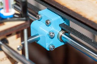
These twisterblocks are really neat, easier than the 'Bananas blocks' I had before.
-
2
- 2 weeks later...
- 1 month later...

Just wondering about this mod. Can this be done without direct drive and if so.. The side blocks, it's a must to change them? Thankss
Just wondering about this mod. Can this be done without direct drive and if so.. The side blocks, it's a must to change them? Thankss
It can. You would just add in 4 extra pulleys, and two shorter belts to convert everything.
-
1
Just wondering about this mod. Can this be done without direct drive and if so.. The side blocks, it's a must to change them? Thankss
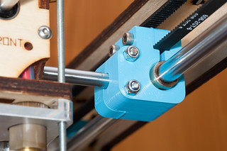
Absolutely -- I am still in 'regular drive' as you can see here:
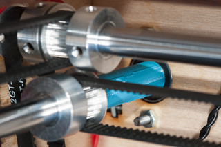
For the short belts you need 101T (202mm) and for the motors you need pulleys with 5mm bore (instead of 8mm)
So in total you need:
- 4 303T belts
- 2 101T belts
- 10 8mm pulleys
- 2 5mm pulleys
You will need new X-Y blocks because the GT2 belts are 4mm shorter so they will be too short for the original clamp system.
And you need to change the pulley ratio in your firmware (same value as for direct drive, this does not change)
-
4
Now that's saved on my to-do-be-do-be-do. Thank you a lot Amedee!
I wonder if this emans that I could use the china-shop side blocks from um2 on this since um2 already uses gt2. That should let me gain (if works) 1 cm of print area. I just ordered x3 of your recipe.
- 3 weeks later...
Finally (just 15 days) mine gt2 belt/pulleys arrived. Enough for 3 machines and a bit of spares 

-
1
One of the few perks of living in china...I use robotdigg and get the parts the next day!
-
1
- 2 weeks later...
Great mod. It's printing quite nice now. I changed the twisterblocks to not loose the 3mm I was losing on the change. Super!

-
1
What 3mm do you mean? I had to alter the twister blocks for the bearings I got, which turned out to be 12mm rather than 11 (OD). thankfully the creator uploaded the STEP files to youmagine.
I mean that with my magnetic heads the size of the blocks are 3-4mm bigger than stock ones so I was losing a little tiny bit of print area. I don't think that happens on the original head. I just moved the holes a bit and cut some. Indeed without the step file it won't be any easy. The blocks are designed really nice.
- 4 months later...

Great mod. It's printing quite nice now. I changed the twisterblocks to not loose the 3mm I was losing on the change. Super!
Hello @neotko,
did you print this in PLA or ABS. And now your Printer is working better than Wood sliding blocks. Also GT2Timing Pulley and Belt Upgrade is must or there not so much Change in Print Quality or something else?
-
Our picks
-

UltiMaker Cura 5.8 Stable released 🎉
MariMakes posted a topic in UltiMaker Cura,
In the Cura 5.8 stable release, everyone can now tune their Z seams to look better than ever. Method series users get access to new material profiles, and the base Method model now has a printer profile, meaning the whole Method series is now supported in Cura!-
- 5 replies

Picked By
MariMakes, -
-

Introducing the UltiMaker Factor 4
ArunC posted a topic in UltiMaker 3D printers,
We are happy to announce the next evolution in the UltiMaker 3D printer lineup: the UltiMaker Factor 4 industrial-grade 3D printer, designed to take manufacturing to new levels of efficiency and reliability. Factor 4 is an end-to-end 3D printing solution for light industrial applications-
-
- 3 replies
Picked By
MariMakes, -
-


Recommended Posts
Top Posters In This Topic
19
15
11
10
Popular Days
May 22
7
Jan 26
6
Jan 27
6
May 17
5
Top Posters In This Topic
lars86 19 posts
ataraxis 15 posts
martin-bienz 11 posts
macua85 10 posts
Popular Days
May 22 2015
7 posts
Jan 26 2016
6 posts
Jan 27 2016
6 posts
May 17 2015
5 posts
Posted Images
lars86 42
I have never tested it, but I would imagine that having mismatched X and Y acceleration settings could do this. Worth checking if you have changed them.
What is your print speed?
You could try slowing the print down to like 20 mm/s and see what the result is.
Link to post
Share on other sites