Jump to content

The physics of cooling?


Recommended Posts

Posted · The physics of cooling?

Playing around with cooling fan arrangements has been sort of a mini-hobby for me, but while I've come up with some interesting and pretty designs that move a lot of air, the results are not significantly better than the stock fan.

Thus, I am wondering if I am perhaps going at it all wrong.

So, back to basics, and a question:

What is the role of the cooling airflow? Is it important to cool the filament right as it comes out of the nozzle, or is it more important to cool the entire layer over a longer period of time?


  • Link to post
    Share on other sites

    • Replies 98
    • Created
    • Last Reply

    Top Posters In This Topic

    Posted · The physics of cooling?

    I've done some experiments with cooling but I still don't feel like I fully understand it.

    I'm pretty sure the fan should only cool the part. Daid I think once mentioned that if the fan cools the tip of the nozzle it can cause problems. I am a little skeptical - I think having the fan cool the nozzle might help reduce leakage/stringing. I don't know.

    I've come across certain prints that are very sensitive to cooling. Most often they are shapes that are clearly defined (like a cube) such that if they are deformed it is obvious. When one prints a Yoda for example, if it is deformed, no one can tell. If his ears are at the wrong angle or his cheek is 1mm in the wrong place even an expert can't tell. But if a square has one rounded corner or is rectangular it is more obvious.

    I found that when I print "too fast" sometimes squares posts are clearly deformed. Especially if the post is at an angle with some overhang.

    Another great example is the UM Robot. When you get to the top, his two antennae print amazingly slowly. If you disable the minimum layer time feature they look like crap.

    Also long ago I experimented with trying to figure out how long it takes PLA to "freeze" just by spinning the extruder, watching string come out, and playing with the string until it seems to harden. It's about 3 seconds with no fan. But it's really hard to measure exactly. It happens very fast and it's subtle. Also this isn't a good test because it's in free air so it cools fast.

    So a few weeks ago I did an experiment. I want to go back to it at some point. Anyway I came up with a very tall and skinny box shape tilted at 45 degrees. This turned out to be a great test piece for cooling.

    I basically concluded that with the fan completely off you need a minimum layer time a little higher than with the fan on but that you don't really need the fan. I got something like 5 seconds with fan, 10 seconds without. Something like that - I posted my notes somewhere else on this forum. I want to repeat the test with my heated bed turned on.

    Anyway - that's just one particular shape/test. There have been quite a few people who have bad tops of their parts if the fan is broken. One person knew his fan was broken and had ordered a new one, the other had the wires backwards and it was sucking air. Lets see if I can find both examples:

    Damn. The search features on this forum suck. For example if I search for "fan" there are zero results. Anyway there was a post within the last week from this guy printing dozens of frogs. After his fan broke they tops looked crappy. A few months ago another guy had his fan sucking. His parts looked exactly like the base in this print where the are holes in the top:

    http://umforum.ultimaker.com/index.php?/topic/2701-strange-effects-on-falt-surface/?p=19426

    Illimuniarti did some experiments and came up with a conclusion that related to both the fan and the infill pattern (the top has to bridge the infill). It's not clear to me in this example (covering up the top of something by bridging the infill with strands of PLA) if the fan needs to blow on the nozzle, the filament, or the part but maybe Illuminarti has something to offer.

    By the way tons (tons!) of people claim the "fan side" looks different. But the fan blows more from *above* than from the side. When the part is *done* printing or almost done it looks like the fan is blowing on one side but as it prints -- the current layer is what is important, not some layer that was printed 10 minutes earlier. So I'm very skeptical about this whole "fan side" thing. But there is something to this claim - I just don't know what it could be. Probably it has more to do with uneven shrinkage.


  • Link to post
    Share on other sites

    Posted · The physics of cooling?

    I think there are a couple of cooling-related issues, and they kinda work against one another.

    In order to print faster, and cleaner, you want to cool the freshly extruded filament as quickly as possible below its glass temperature. This should help with bridging and overhangs, and also prevent the sides of prints sagging under gravity when printed fast such that heat is getting added faster than it is lost.

    On the other hand, in order to prevent warping, I think you want to minimize overall cooling. This plays into the 'side away from the fan' discussion. I find that if I have large flat things are likely to warp up off the bed, this is most likely to happen on the right side of my print (my fan is on the left of the head). Contrary to the received wisdom about the 'side away from the fan' being cooled less, and so printing worse - I think it's the opposite. That side of the print gets more overall cooling, but at a slower rate. Because wherever the print head is, if the fan is on, there's some amount of airflow over that side of the print. The left side of the print gets cooled less overall, because much of the time it is below and behind the fan opening, and only gets blown on when the head is on that side of the printer.

    This interpretation would seem to be supported by the fact that when you turn off the fan totally, the warping gets better, or often goes away, rather than getting worse.

    However, you should also bear in mind that, at the moment the filament is laid down, it is always a constant distance from the fan opening. The amount of time it spends in the most intense cooling air stream will depend on the direction the head is moving. For a fan-on-the-left set up like mine, with the nozzle towards the front of the head (and hence fan opening), extrusions spend least time in the air stream when printing from left to right (as the extrusion quickly passes under the fan), or from front to back (as the extrusion passes out of the airstream quickly as the head moves towards the back of the printer).

    Conversely, when printing a line from back to front, the fresh extrusion gets probably the most immediate cooling, as the entire length of the fan opening passes close by it. Segments printed right to left probably also get cooled quite well, since although the fan is moving away from the extrusion, it remains in line with the air stream and so gets some smaller amount of cooling for longer.

    I suspect this may be the root of the 'side away from the fan' mythology... if printing loops in an anti-clockwise direction (which used to be fairly typical - SteamEngine mixes it up a bit at the moment) the left side of the print 'nearest the fan' gets the most intense cooling, while the opposite side gets much less. Hence improving short-term performance on bridges and overhangs. But in the long term, that side tends to cool faster, and so warp more.

    So overall... I think the best way to test cooling effects is to look specifically at what difference it makes to minimum layer times, bridges and overhangs on perimeters. It may well be that actually, cooling is best used targeted to just loops and bridges (including the transition from sparse to solid infill). And then turned off for (non-bridging) infill, in order to slow down the overall cooling and help reduce warping forces. Kisslicer for one allows fan speeds to be set independently for these.

    On the issue of blowing on the tip... it really depends what you are trying to achieve. I've certainly helped troubleshoot at least one user who had a dysfunctional fan shroud that was cooling the nozzle tip quite heavily to the point where his prints were coming out really badly, and having lots of jams. At the end of the day, all it's doing is lowering the extrusion temperature, so that while you think you're printing with 220º plastic, in actual fact you're printing with 180º plastic. So it's going to flow less well, and take higher pressure, and so under-extrude more. If what you want is cooler plastic, probably best to just lower the overall temperature - because with a cooled tip, while extrusion is harder, and pressures higher, you do still have a reservoir of very molten plastic at even-higher-than-usual pressures that might be looking for ways to squeeze back up into cooler parts of the head and cause problems.


  • Link to post
    Share on other sites

    Posted · The physics of cooling?

    I agree it is a very complex issue, and the design of the UM hotend does not make it easy to come up with good shroud solutions, because the heat block really gets in the way.

    One thing I have played with but need to work on some more is isolating the hot end from the cooling airflow, because the last thing you want is air passing the hot-end, heating up, and then flowing over the part -- it defeats the purpose.

    I have tried several solutions but I think perhaps the most promising one is a box that fits around the hot end with a fan that sucks air into the box via the nozzle area, thus blowing the hot air up and away from the part. Then we might be able to go with some fans or ducts that are attached to the UM frame, which would have the nice side-effect of slightly reducing the hotend mass.


  • Link to post
    Share on other sites

    Posted · The physics of cooling?

    The tip cooling thing just happened to me, just now. I was doing a print in LayBrick. Started off really great, with even extrusion. By the second or third layer, there's visible under extrusion - the solid infill has gaps. I slowed down 15% and upped the flow 15%, neither made any difference at all. Then I noticed that my printed fan shroud has worked a little loose, so might be blowing across the tip now. Turned off the fan - and within seconds, extrusion is perfect again.

    LayBrick requires fairly cool and slowish printing to begin with, and I was printing towards the lower end of its range - the additional cooling of the fan was enough to restrict the flow significantly, it seems.


  • Link to post
    Share on other sites

    Posted · The physics of cooling?

    I have experienced poor printing due to cooling of the nozzle and have since put on a silicon jacket around the nozzle and heater block which fixed the problem. I agree with illuminati about cooling required for bridging but causing warping effects. Also it's very filament type dependent. ABS will need much less fan for bridging but does seem to need some, though as soon as the fan comes on it starts to lose it's grip on the platform due to warping. That's my experience so far after my first attempts with ABS. HIPS filament on the other hand remains gooey for so long without a fan so the print goes terrible. All though I've read HIPS is similar to ABS I am getting the HIPS to stick very well by putting 2 fans on at 100% from the first layer. PLA seems to be between these two extremes. btw I'm new to HIPS as well and my results improved markedly when I made an enclosure for the UM.


  • Link to post
    Share on other sites

    Posted · The physics of cooling?

    Can you give more details about the silicon(e?) jacket?


  • Link to post
    Share on other sites

    Posted · The physics of cooling?

    I made a mould (printed block and nozzle and outer shell around that) and squeezed silicone from a tube into it. It's held on with a cable tie and unfortunately it's not high temp silicone so it has went off color a bit and looks a bit dodgey but functions very well. I have seen that Jorgen has one that looks like it's made from silicon mat or something not sure and someone else has one too.


  • Link to post
    Share on other sites

    Posted · The physics of cooling?

    Thats a pretty good idea to make the mold Owen. Is there a permatex silicone form-a-gasket product that could be used for this?

    Edit:

    Looks like this stuff could work. http://www.permatex.com/product-selector?view=productcategory&id=170 and I think I have some of it left over in the garage...


  • Link to post
    Share on other sites

    Posted · The physics of cooling?

    I think that would work. You see a lot of this one http://www.ebay.com.au/itm/81160-Permatex-High-Temp-Red-RTV-Silicone-Gasket-Goo-Maker-/350866532622?pt=AU_Car_Parts_Accessories&hash=item51b146690e on eBay which I think would be good too. The mold I made pushed up from below and because of the cables at the back of the heater block it didn't wrap around real well which is why I had to use a cable tie to hold it on. If I were to do it again I'd make it push on from the front. If you're thinking of having a go you should slightly undersize the plastic heater block and nozzle so the gasket will then have to stretch over them.


  • Link to post
    Share on other sites

    Posted · The physics of cooling?

    Did you grease the mold before filling? Or some kind of powder for mold release?


  • Link to post
    Share on other sites

    Posted · The physics of cooling?

    Why not make an oversized shell (2-part), fill it with some of the silicone, and use the actual hot end to cast the inner surface of the silicone. Then unbolt and remove the shell, do a little trimming, and you should have something that fits like a glove.


  • Link to post
    Share on other sites

    Posted · The physics of cooling?

    Did you grease the mold before filling? Or some kind of powder for mold release?


    Yep. I used vaseline petroleum jelly. Printed in PLA


  • Link to post
    Share on other sites

    Posted · The physics of cooling?

    Why not make an oversized shell (2-part), fill it with some of the silicone, and use the actual hot end to cast the inner surface of the silicone. Then unbolt and remove the shell, do a little trimming, and you should have something that fits like a glove.


    I thought about that but those parts were easy to make in cad and print and you nearly need them in your cad program to make the shell. I also wanted to make them slightly undersized so the gasket would stretch. Plus the cables would get in the way. So parts are re-usable to.


  • Link to post
    Share on other sites

    Posted · The physics of cooling?

    Kapton tape wrapped around all of the hot components seems to work well.

    As for the physics of cooling. The way a fan cools plastic is similar to the reason wings work. I can get into this in more detail if anyone wishes but what I am getting at is that in order to achieve proper cooling (dissipation of thermal energy), you must have an air stream blowing in contact with the molten plastic but across it; not directly at it as this is less efficient and could cause it to bend more while it is still malleable (in an overhang situation) due to the shear force of the increased concentration of air molecules. I have found that PLA cools best when you use this fan duct: http://http//www.thingiverse.com/thing:69327

    I recommend you wrap the hot components with some sort of insulator when you use this duct because it doesn't entirely avoid blowing air on the nozzle.

    I have also found that improved cooling by means of a fan helps with elevated ridge mid-print warping and upwards curling (not build plate adhesion warping). I printed several tests and simply having the fan on during those layers eliminated the warping completely (with the aforementioned fan duct). I still had a little warping with the stock fan duct before I switched to the better one.

    As for the physics of the whole thing, I am not completely sure why cooling helps with curling but I think it is a layer adhesion and filament strand strength thing. It will bend more easily if it is still molten vs. entering preliminary cooling stages.

    Anyway, those are my thoughts. What do you think?


  • Link to post
    Share on other sites

    Posted · The physics of cooling?

    ... investigating in this issue as well.

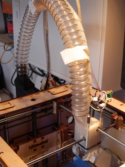
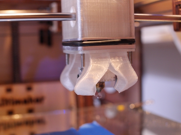
    Since lately, I'm able to throw a lot of cool air almost concentric beneath the nozzle. The current setup is good for printing scottvader's racing vase with up to 100 mm/s with perfect surface all around (BTW: printing speed doesn't translate to layer time because the - ugly - seam takes considerable additional time).

    But I'm still far away from knowing what is exactly happening and why. Bridging and printing overhangs works considerable better. But I also get a huge "ground effect". If I turn on the fan below 2-4 mm height there is a massive temperature drop (> 10°C). Almost nothing happens at greater heights, so the cold air doesn't reach the nozzle directly but after being reflected by the print bed.

    However, the object geometry has a massive influence. It not only affects the amount of thermal input in certain areas (e.g. slower moving print head in tight corners) but also how much cooling air can reach those areas (e.g. how fast the print head with the attached cooling moves away ).

    new-printhead.jpgnew-printhead-detail.jpg


  • Link to post
    Share on other sites

    Posted · The physics of cooling?

    @foehnsturm - Very interesting that you can do 100mm/sec and Scottvader can't. I'm more interested in your layer time than print speed. Did you time how long each layer takes?

    I've done a similar experiment on a similar part as I said above and I see the same issues at similar speeds that scottvader shows on that racingvase link you posted above. My part was smaller so the fan was always giving it good air. Except when I turned off the fan.

    I'm not patient enough to print an entire vase for each speed test so I just changed the speed every 30 layers or so.

    By the way - regarding the z seam - illuminarti had a great post and I followed his advice and increased my Z acceleration from 100 mm/s^2 to 400 mm/s^2 (not the 1500 he uses!) and the Z movement is almost just a "click" now it is so fast. More importantly the z seam is better (not perfect but much better).

    http://www.extrudable.me/2013/04/02/the-myth-of-z-speed/

  • Link to post
    Share on other sites

    Posted · The physics of cooling?

    That looks cool foehnsturm

    what's the tube called and where can I get it?


  • Link to post
    Share on other sites

    Posted · The physics of cooling?

    @owen,

    Just look at http://umforum.ultimaker.com/index.php?/topic/2435-new-fancooling-design/ (lower half)

    @gr5,

    I'm planning to do some test prints with my camera running. Just have to find the time. So far I used exactly scottvader's cura settings. I will try your z setting (only doubled the default so far). The funny thing is, when printing fast enough you not only get the ugly blob but also a hole thereafter, because of the pressure plunge in the hotend. I'm wondering if slicers could handle the pressure drop at z movement a little smarter.


  • Link to post
    Share on other sites

    Posted · The physics of cooling?

    A quick test run with old cura and joris enabled.

    The silicone pad almost eliminated the temperature drop when cooling at low height.

    There is still room for improvement as only one side starts to show small artifacts at high speed.


  • Link to post
    Share on other sites

    Posted · The physics of cooling?

    Just an update of my own. I've https://www.dropbox.com/sc/ilt34t2thwoqfxh/HuBbezJX_Y for creating silicone hotend sheathes and have a test sample curing. One issue with HTV silicones is that they cure by exposure to atmospheric moisture, so it may take a while for the part to cure given all the internal surfaces -- patience is a bitch.

    I cooked it overnight in a rice cooker set to warm inside a jar with some water in it to provide humidity, but I think I'm going to let it go another 24 hours before I crack it open.

    Worst case I'll have to get some of the 2-part mold-making silicone that uses a catalyst, or perhaps http://www.tapplastics.com/product/mold_making_materials/mold_making_supplies/silicone_putty/563.


  • Link to post
    Share on other sites

    Posted · The physics of cooling?

    Has anyone tried this with Sugru?


  • Link to post
    Share on other sites

    Posted · The physics of cooling?

    Just an update of my own. I've built a mold for creating silicone hotend sheathes and have a test sample curing. One issue with HTV silicones is that they cure by exposure to atmospheric moisture, so it may take a while for the part to cure given all the internal surfaces -- patience is a bitch.

    I cooked it overnight in a rice cooker set to warm inside a jar with some water in it to provide humidity, but I think I'm going to let it go another 24 hours before I crack it open.

    Worst case I'll have to get some of the 2-part mold-making silicone that uses a catalyst, or perhaps something like this.


    Looks good MadOverlord

    My first go I only waited about a day and it was too soon. 2nd go I waited 3 days and that was long enough.


  • Link to post
    Share on other sites

    Posted · The physics of cooling?

    Has anyone tried this with Sugru?


    Sugru is only good to +180c, and likes to bond to metals and some plastics, including ABS.


  • Link to post
    Share on other sites

    Posted · The physics of cooling?

    I read up on Oogroo, a home-made Sugru replacement:


    I do not know about the heat resistance, but the interesting aspect was using corn starch as a carrier for the moisture, which will cure the silicone within minutes all the way through (speed depends on the amount of starch)


  • Link to post
    Share on other sites

    Create an account or sign in to comment

    You need to be a member in order to leave a comment

    Create an account

    Sign up for a new account in our community. It's easy!

    Register a new account

    Sign in

    Already have an account? Sign in here.

    Sign In Now

    • Our picks

      • UltiMaker Cura 5.8 Stable released 🎉
        In the Cura 5.8 stable release, everyone can now tune their Z seams to look better than ever. Method series users get access to new material profiles, and the base Method model now has a printer profile, meaning the whole Method series is now supported in Cura!
        • 5 replies
      • Introducing the UltiMaker Factor 4
        We are happy to announce the next evolution in the UltiMaker 3D printer lineup: the UltiMaker Factor 4 industrial-grade 3D printer, designed to take manufacturing to new levels of efficiency and reliability. Factor 4 is an end-to-end 3D printing solution for light industrial applications
          • Thanks
          • Like
        • 3 replies
    ×
    ×
    • Create New...