

I personally dont care how the Design looks...... i just care about that it works perfectly and with less hazzle and maintance. Efficiency>Looks 

I personally dont care how the Design looks...... i just care about that it works perfectly and with less hazzle and maintance. Efficiency>Looks
Here is my opinion on this, as a user of UM1 for 2 yr and having modified the heck out of my extruder drive to get it to work reliably.
Take it or leave it obviously.
I think the knurled thing has to go. I was never able to get a good extrusion until i made my own hobbed bolt with sharp teeth and a larger diameter (using a metal "spacer" as the blank like the makerbot mk6 drive gear)
I think the 'lack of space' for the spring to travel is actually a good idea. What this does is it creates a stopping point for the travel of the sprung idler. This means that if the drive grinds the filament because of too much pressure needed to extrude, it does not go on ahead eating away at the filament (as the spring idler presses it in towards the drive gear). Also consider the problem of force application. With a totally sprung idler (no stop) the spring is squeezing the filament towards the drive gear, in a direction it totally does not need to. With either a fixed idler (like the first wade's extruder) or a stopped idler, the pressure stops after teeth have been imprinted on the filament, because after that point you don't need to press on the filament even harder. Just another point on this: we don't need the drive gears to accomodate all sizes of filament. The bowden tube already jams if the filament is the wrong size. That is why a minimum travel of the idler wheel should be fine (in fact my extruder currently has absolutely no travel and it works great with ABS and PLA)
I think the extruder needs a gear reduction. This allows you to use larger diameter drive gears which I think are absolutely necessary to have enough grip. The goal is to have the extruder motor start skipping before the filament shreds or the hot end gets destroyed.
finally, other aspects of the filament drive subsystem are important to consider. For example, the length and ID of the bowden tube, the hot end itself (modified to minimize necessary extrusion pressure?), and of course the diameter of the filament you are feeding into the machine (forget it if the filament ever goes near 2.99-3.01mm). If any of those other things don't fit the specification then nothing you do to the pinch wheels will make a difference.
Here's the files for my monstrosity for those that want to have a look: https://www.dropbox.com/s/1azjgc5tgr39v5l/iroberti_extruderExperiment.zip
Ya know... sometimes trying to draw things that need to fit specific conditions makes you want to kick kittens... Had a good idea going, spent a few hours on it, started putting the parts together in an assembly and then BAM, Murphy comes along "Nope, f**k you Rob, you thought that would fit? Shouldn't you know better by now?".
*sigh*
I studied a little question.
1 / It is doable in 2 screws.
2 / It should be reversed position of the actuating system such that the toothed pulley is left. The filament just left, pulling it on impulse withdrawal pulley that is spring loaded against the drive pulley. In revanchee if Conversely, the more the thread pulls, the more it hangs. By doing so, one can easily guide the yarn and was more loss as before. Idea to dig.
3 / Add a pulley to guide the wire and keep it from blowing instead of passing through a track. Idea to dig.
For now I'm here. I'll see tomorrow if I can redesign a some-thing correct. But I emits a lot of doubt on the reliability.
I think that the position of the motor, the drive system is not optimal.
How does the extruder UM1? Do we have plans?
I can't speak for anyone else but I'm having a real hard time understanding your last post Geeks. Google translate isn't all that great sometimes...
Even if I do not own a UM2 yet, I'll try to contribute a little bit.
Are you familiar with the MIG/MAG welding machines?
If not here a short explanation:
In this machines a wire is fed thru a several meter long bowden spiral or tube up to the welding nozzle.
First machines which are 50 years old had quite weak feeders causing lot of problems if the friction of the wire in the bowden tube raised for a reason. So later the manufacturers made over the feeder system and a two wheel feeder became standard.
There are some variations on the market with different numbers of wheels and friction wheel desings.
The idea behind this post is to look which solutions other machines with similar features have to offer.
If you think this might be a way I can offer to look after some designs. Maybe there are some hints insice that could contribute to the solution.
So long
nudel
Interesting subject!! I have been looking at how to further improve the UM1 extruder drive but as usual I am running out of time. I did not realize that UM-2 has changed to direct drive. If I am going to play with this, I might as well go in that direction to be up-to-date.
Any suggestions for finding the stepper in the USA and knurled wheel? I am not too enthused with the knurled wheel but it could be a starting point.
Bertho
How appropriate that Bertho showed up just as I was uploading pics of my latest progress (?)  I'm blatantly stealing your idea and trying to make it more compact to fit on the UM2.
Still early, but it kinda sorta looks like it might possibly maybe work. But for now my brain is completely fried, I need sleeep.


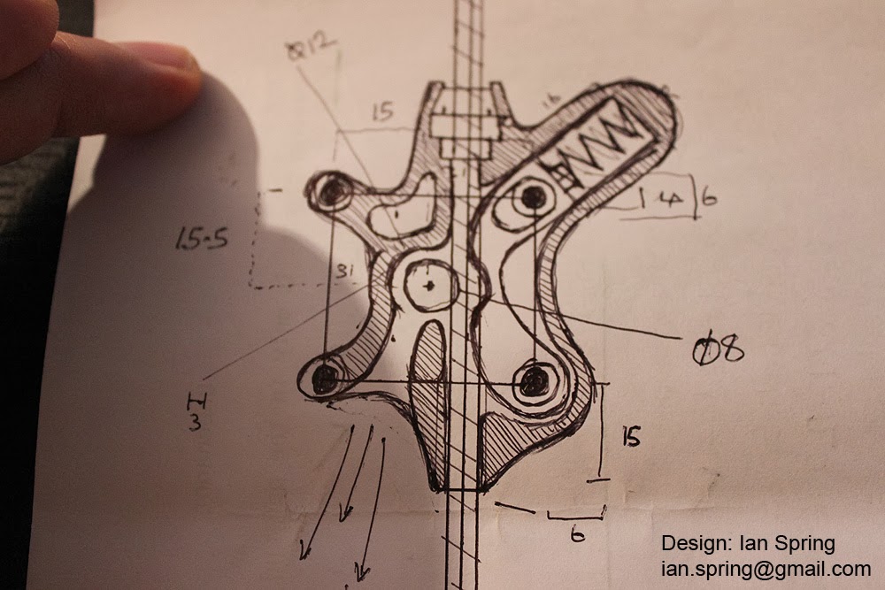
here is one idea I have.
using a larger single spring mechanism with a spring damper. Another nice design feature is the bottom whole to release loose particles of filament out of the extruder housing :smile:
There are some good design elements here. I really like the idea of a place for the filament bits to exit.
I disagree with the piece on the right side though. The point of the part that pushes the filament against the knurled head is to provide as little friction as possible in the linear direction of the filament feed.
This design has two contact points where the current UM2 has one contact point. This design also has static contact points that will provide much more friction than the wheel in the original UM2.
Finally, both this design and the movie reel one you showed apply offset pressure to the filament. Over time (users who leave filament in the machine while not in use) a static filament will bend/warp in this design which will then cause issues when this curved portion exits the extruder housing or along the path of the bowden tube. It would take only a very small kink in the shape of the filament to cause friction in the bowden tube which is already VERY tight if you are nearing 3mm filament thickness.
I think this basic design is still very valid, it is nice and simple, but I think that the contact point that puts pressure on the drive bolt has to be exactly opposite the contact point to avoid any tendency to bend, and that contact point should be as much of a low friction point as possible.
I definitely agree that the diamond design of the knurled metal piece is sub optimal.
Another idea to improve contact along the filament would be to increase the diameter of the knurled knob/bolt/whatever. This is not a simple change as that would change torques and the linear travel distance of a step (which would require software changes of some type).
Very cool to see this open discussion!
How appropriate that Bertho showed up just as I was uploading pics of my latest progress (?)
I'm blatantly stealing your idea and trying to make it more compact to fit on the UM2.
Still early, but it kinda sorta looks like it might possibly maybe work. But for now my brain is completely fried, I need sleeep.
I really like the look of this. I can't easily tell, but it looks like the opening below the drive wheel is quite open so that any flecks of filament produced can easily fall out the bottom. Along with your bearing upgrade to the feed wheel you might be on to something here.
:oops:
I can't speak for anyone else but I'm having a real hard time understanding your last post Geeks. Google translate isn't all that great sometimes...
I do my best ... :???:
Thank you all for cooperating in such an constructive manner in this topic. The feeder is not perfect yet and rest assured that we are looking into improving the feeder mechanism. We do have limited resources, which have been strained to the limit due to the exceptional success of the UM2.
We grew into a the company that we are to day, because we have a very supportive community. So if there are any fixes or improvements from the community, we will contact the respective designer(s) to discuss how to incorporate their design into our machine.
Best regards,
Harma Woldhuis
Coordinator for R&D
Ultimaker
 1
1
Good idea, even though I am not a UM2 user (but a long time hacker of UM1 with hundreds of hours experimenting with filament feeders as many others).
There may be a few ideas to grab from the extremely reliable one I have been extensively using for the last year, and which I published in details here: http://www.tridimake.com/2013/04/rollerstruder-filament-feeder-driver.html
Actually I switched last weeks to a new and major revision that addresses a few things (mostly feature requests I got). I am not sure it is more reliable though, I will post about it as soon as I have analysed it enough.
Check also the hobbed bolt may be, I just don't think that the default "grinders" that comes with the printer are that good. I talked about it here: http://www.tridimake.com/2013/03/which-hobbed-bolt-for-filament-feeder.html
Now I cannot agree more with the idea that it should better be the stepper that stalls before the filament is damaged. Too harsh a grip is just useless or even counter productive: better tune the flow correctly! See eg, http://www.tridimake.com/2013/05/no-slipping-no-grinding-not-always-good.html
Finally I just like the big gear, simply because I can tweak and FEEL the tension by hand, or even fix a hiccup in real time. I do not think it is possible with a direct drive. Sure, it makes the thing bigger overall, but this is a price I gladly pay compared to a "self contained hidden" mechanism... Which is also why I favor "open" designs, where the filament can be changed and swapped in no time. Finally, I no more trust the push fit, and I better like blind rivets on the bowden tuben with a printed plug that slides in place.
I really like the look of this. I can't easily tell, but it looks like the opening below the drive wheel is quite open so that any flecks of filament produced can easily fall out the bottom. Along with your bearing upgrade to the feed wheel you might be on to something here.
Yes, it's open underneath. The bearing is already present in the original design on the UM2. I realised when you pointed it out that I haven't added the grooved ring I was planning on putting around the bearing to guide the filament though. Since I want nothing in the housing touching the filament I realised I needed something more besides the bowden to prevent the filament from slipping off. The simplest thing I could come up with was to have a groove on the idler.
I was also thinking about the "big gear". It seems illogical to me to use a direct drive extruder for a bowden system.
We don't care about weight, and shouldn't care too much about size either, except for aesthetic purposes. But we do care about torque. Since we have a tough motor, even a significantly smaller gear ratio than the UM1 would work wonders for reliability I think.
As for friction, as I understand it, this problem is caused primarily by the position of the extruder vs. filament spool, so the filament gets bent 90 degrees before entering the extruder. My question is, since I don't have an UM2, can the extruder somehow be mounted higher, to lessen the angle of the filament and reduce friction at the entry point?
You can move it to wherever you like just as long as the cable harness for the motor is long enough and you add spacers between the motor and extruder housing if you don't have the side panel in between.
As for friction, there's a fair amount of friction inside the actual extruder. I uploaded a few pictures a while ago but didn't make them public at first. Here they are:


Whoa, that looks really bad!
BTW, Robert, would it be possible for you to provide your extruder in STEP format?
That goes to all future uploads to this thread, too. Please use .STP if available in your software.
Sure, I can do that. But no point in uploading my current design yet as it has quite a bit to go before being ready for a beta print.
Not for printing, but just so I can snatch the measurements, since I don't have an UM2 here.
might it be possible to get the original extruder design as .stp or .igs file?
I have no UM2 in reach to take a proper measurement. Is the data eventually in the open source download section? I had a look there but wasn't able to recognize, so maybe I missed this somehow...
If I had such data, I would take this as starting point, working in a different feeding system.
Sounds like a good idea to help the UM guys to improve a little.
cheers
nudel
I see the need and concern for allowing ground filament bits to fall out of the way.
Providing such clearance seems a stop gap measure. The source is that the drive wheel abrades the filament. Prevent that, and the problem is solved.
I submit again, the drive form used in the GoeHagen extruder. It is essentilly the same as the one featured in the blog linked on page 2 of this thread, but larger OD.
The larger OD reduces output force compared to the standard UM1 extruder, but it is not a detriment. The larger diameter also increases the contact with the filament.
The big gear set-up is good from a 'manual' standpoint, for the added torque from the reduction. Maybe the higher resulting extruder resolution is also an advantage. IDK.
For argument sake, the 'accessible wades extruder' has a lot going for it - although a bit dated....
I know the intent here is to use stock parts and to make the fix fully printable, but in the thread in this folder regarding flexible filament, there is a link to what appears to me to be a much better knurled bolt/knob/thingy.
http://www.ebay.at/itm/281102410932?ssPageName=STRK:MEWAX:IT&_trksid=p3984.m1423.l2649
I don't know if the radii match, but the design is great, with the notches fully perpendicular to the direction of motion and the shape keeping the filament in place.

ArunC posted a topic in UltiMaker Cura,
.thumb.jpeg.0b7a05eafc09add17b8338efde5852e9.jpeg)
Dustin posted a topic in Firmware,


Recommended Posts
Top Posters In This Topic
120
118
52
37
Popular Days
Feb 10
33
Feb 25
29
Feb 13
26
Mar 27
23
Top Posters In This Topic
ian 120 posts
IRobertI 118 posts
Blizz 52 posts
geeks 37 posts
Popular Days
Feb 10 2014
33 posts
Feb 25 2014
29 posts
Feb 13 2014
26 posts
Mar 27 2014
23 posts
Posted Images
IRobertI 520
@Takei: The idea was to put a screw through the lever and have that push on the spring. Ideally I wanted to mount the spring directly to this screw but didn't have anything at hand to do that.
I got your PM about wanting the files. I'll get them up in a bit.
I've started over with a "new" idea now and I have to say I reaaallly hate that the side panel sticks out on the backside... It steals so much thickness from the design :/
Link to post
Share on other sites