

200 mm/s at 220 °C is quite impressive.
Thanks for the photos!

very interesting. So if we sum up all the info from those tests, for the best looking result (stringing, overhang and under extrusion) if you're not in a hurry, the best is to print at temperature around 180 C and at low speed. Right?
no and no. lol.
1) Printing at 180C is more likely to clog and worse, if your PID isn't perfect you could hit the trip point where it shuts off the ultimaker. So I don't plan to go lower than 190C. And other brand/colored PLA might not need to be so cool to not-string.
2) I'm going to do more overhang tests but I realize now that the problem with the overhangs wasn't speed so much as giving the plastic time to cool. So I'm going to print larger parts and I suspect I can print faster.
So speed might not be much of an issue for overhangs.
On parts with no stringing possible (e.g. no gaps, no towers, no retraction needed) I plan to keep my temp higher and my speeds higher.

Picture posted at the request of gr5
gr5 edits:
Text from above picture:
bottom left: feeder spring 13,61mm (used until now)
bottom center: feeder spring 13,81mm
bottom right: feeder spring 16,42mm (sign of underextrusion)
top left: after small belt tightening
top right: after long belts tighten...
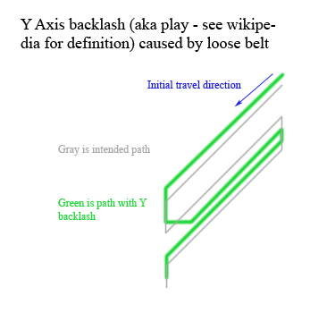
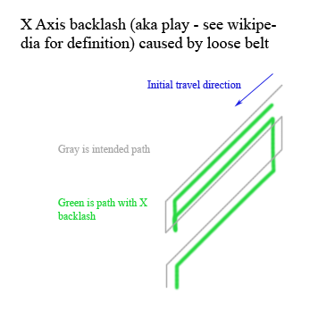
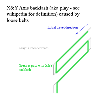
How does loose belts (backlash) cause gaps in diagonal lines you might ask? Here are some diagrams to help explain. Please don't tell me the diagrams are wrong without spending at least 30 minutes drawing it out very slowly and carefully like I did. Start with the Y axis backlash only diagram as that is the simplest one, the move onto X and then XY. In parts of these, the head isn't moving at all, or retraces it's path so the picture doesn't tell you everything that is going on but it does show the path of the nozzle.
 1
1
Extremely interesting stuff. *subscribed*
This picture clearly shows the difference that a lack of cooling makes when covering over infill.

Top print is PLA at 225ºC, 75mm/s, 0.1mm layers, 20% infill, 1.0mm top thickness, sliced using Cura 13.06.5.
Bottom print is exactly the same, except the fan was turned off for the entire print, resulting in the plastic bubbling up as it tried to cover over the infill, and a failure to fully close in the top surface.
The first layer of solid infill is unlikely to print well, because of the gaps involved. The extrusion only sticks for a few mm as it crosses the infill lines. With cooling, those short stretches of infill either side of the infill lines form a flat-topped platform that reduce the gap slightly, so it becomes easier and easier to close up the gaps on each pass. Without the cooling, when the first layer of extrusion hits the infill lines, the bottom of the extrusion sticks, while the top keeps moving for a few mm. This has the effect of pulling on the trailing blob of plastic, curling it upwards so it sticks up above the print level. This provides a rough, springy, sticking-up base for the subsequent layers to try to print over, resulting in an incomplete, bubbled up top surface, that even ten layers of solid infill can't cover over.
Moral of the story: if you see an uneven or incomplete, bubbled-up surface on horizontal top surface, make sure that your fan is working properly, and delivering enough cooling air to the print head.
Great insight Illuminati! I had that problem many times, and could only diminish it by increasing the infill percentage, so that the gaps were shorter. Now I realize why so many people use bigger/more cooling fans.

Is there an .stl file for a fan duct that anyone particularly recommends to help with the aforementioned overhangs? I am currently getting good results with http://www.thingiverse.com/thing:69327.
That fan duct looks very good. You don't want to restrict airflow much as these fans aren't good at that. The only improvement I can think of is to have one on each side like the um2.
Bridge test. Only temperature seemed to make much difference. With the exception of the 230C print, all the drooping filament was caused when the hot end damaged an existing bridge string. In other words each string was laid down PERFECTLY. But then a few seconds later the hot end would mess up a previous string.
Sliced in Cura 13.10. No special settings. Temperature seemed to be the critical factor. Cura slices the first layer along the length of the string and then prints normally after that: skin/walls first, then diagonal infill.
Walls were at .8mm (two passes). stl is 50mm bridge here:
http://www.thingiverse.com/thing:12925
As usual, this image is bigger than your monitor. To zoom first click the image, then right click and choose "view image" then click a third time for the FULL zoom. Pan around the image with scrollbars.

75C Bed Temperature is too hot!
60C to 70C works great. 75C bed temperature caused the problem in this photo:

1
Hi, I have also done some work on finding optimal settings. My method was not yet described on the forum, so I made this post describing the steps. http://umforum.ultimaker.com/index.php?/topic/5093-how-to-setup-print-speed-temperature-and-layer-height/
Hope it is usefull
Fantastic photo from boraxflux showing relationship between bed temperature and why 75C is too hot. This is caused because the filament doesn't have enough time to cool and so it is pulled inward like string as it is being laid down. This has nothing to do with shrinkage due to cooling.

Oh that picture is a great find. I had printed the cylinder myself and had the same problem as the pic at 70-degrees. Is it just me or does the 50-degree temp look the best as it has the least amount of warping at the bottom?
Also, newb question here: do I need to press tune every time to adjust the hardware settings, or does the UM2 retain the settings from the last print, or do I just use the Tweak at Z plugin every time?
This "shrinkage" is not shrinkage at all. It is how it was printed. Imagine the filament coming out of the nozzle as a rubber band. It pulls is it comes out of the nozzle and if you print a circle it pulls inward. If you print a zig zag, it will cut every corner. The problem has more to do with the fact that the layer below is still soft and bends. So instead of thinking of that as shrinkage think of it as "too soft to stay in place". Instead of lowering the bed temp you can simply let it cool a little longer - those printed cylinders only were about 5 seconds per layer with fan off and you need more like 10 seconds per layer to avoid any "to soft to stay in place" issues. So simply adding infill, or slowing it down some more would do the same thing as lowering the bed temp. Or turning on the fan sooner.
1
great thread, thanks!
I bought my Ultimaker 3 a couple of months ago and have been regularly printing various models since. Initially I started printing support structure using PVA, but since this increased the printing time very considerably, I decided to try printing the support structure with the model filament itself. The results are amazing, the surface is incredibly smooth with no evidence of support structure having been used. I did however notice some stringing occurring on the support itself. Since this didn't attach to the model I haven't bothered making any adjustment settings. But I've always believed that the filament colour has an effect on such occurrences - I've only used PLA so far (Ultimaker brand and ColorFabb). I've printed flat print-in-place models successfully and the parts moved immediately as they were removed from the print bed. However print-in-place models with integrated ball joints could pose a problem with possible stringing. One model failed (articulated puppy dog) after two goes at repositioning on the print bed - the limbs did not move, they broke off. If I make adjustments to the settings, am I likely to resolve stringing on the support but then adversely effect the model surface quality?
It's not clear that your problem with this ball/socket joint is because the ball and socket are being printed too close together or if there is stringing. With stringing I would lower temp. But more likely it's ball touching. Maybe you should have taken a photo when it was printing the ball and socket to show how closer they were or if there was excessive stringing in the joint.
Anyway there is a parameter called "horizontal expansion". If you set that to -0.05mm you can increase the gap between ball and socket by 0.1mm.

ArunC posted a topic in UltiMaker Cura,


ArunC posted a topic in UltiMaker 3D printers,


Recommended Posts
ian 32
very helpful comparison material and guide ! thank you for your work and help !
Its interesting trying to push the ultimaker to the best formula between layer height, speed and temprature.
Ian :-)
Link to post
Share on other sites