

foehnsturm 969
Is there any new information about the max. current, the fan drive can handle?
I want to test a fan with 0.4 Amp.

Is there any new information about the max. current, the fan drive can handle?
I want to test a fan with 0.4 Amp.
You should have no problems. I have a .55A (6.6W) 40mm fan that I have used in tests -- alas it screams like a jet engine.
Thanks!
Works fine - and doesn't scream.
I only had to set cura max fan settings to 40%. Otherwise the PWM driver seems to operate the fan (8-15 V, 0.4 Amp @ 12V) way beyond its specs.
Interesting. I put a voltmeter on the fan supply and to my surprise it provides 18v. I was under the impression it was a standard 12v supply. This means that the standard 50mm fan is being overvolted.
To get 12v you set the fan speed to 150.
PWM signals seem to have different effects on different motors. My voltmeter showed irritating 7 V all the time but with fan settings beyond 100 current raised to 0.6 A and more Amp and the fan blew way more than when connected to a stabilized 12V supply.
255 should be mapped to a full-on duty cycle, so you are right, with the overvolting.
Voltmeters in DC mode (or even AC mode) do not measure pulsed signals very well. PWM in this case means the fan is turned on and off many times per second. The voltmeter is probably designed to measure DC voltage so it gets a bit confused. Tries to average but probably fails.
I've actually found them to be fairly accurate, especially when you have a load in the circuit. If you want to get things a little smoother, just put a ceramic cap in parallel.
Side note, I just published a hopefully useful hot end utility mount that does not interfere with either the sliding blocks or most existing fan mounts, and lets you mount things on all 4 sides of the hot end -- in particular, it makes it easy to mount vertical 40mm and 50mm fans.
http://www.thingiverse.com/thing:164499
I apologise for the delay in posting this, but I ended up doing all sorts of experiments before finalizing the design of the hot end thermal isolation sock.
Here it is: http://www.thingiverse.com/thing:165750
Looks great MadOverlord. Is it for the V1 or V2 Hotend?
I got my Ultimaker in the spring, so v2 I would suppose.
I got my Ultimaker in the spring, so v2 I would suppose.
Cool. I'm going to make it. Mine has deteriorated a bit lately and I've had to use a bit of kapton tape to hold it together. It still does the job but this covers the whole block much better than mine did so I'm going to upgrade.
Yes, it just locks naturally into place. I went through a bunch of iterations to get it to be a nice fit.
I have been lurking on this discussion. I made a similar boot for my homemade hot end. I did try mixing in some corn flour to hasten the cure. Actually, in the states corn flour is a bit hard to come by so I used "corn meal" and turned it into flour in my coffee grinder. I'd say I mixed it at 1:3 to 1:4 flour to silicone. Probably a more saturated mix than necessary, but didn't seem to hurt any. I then mixed it well on a paper plate with an old credit card. I designed a fill port and opposing vent port into the mold. Used a 50cc utility syringe to fill the mold. It cured in about 20-30 minutes
I've just finished the one from MadOverlord. I put it in a jar with a wet sponge on something warm. It was very humid in there but still took for ever to cure. I haven't printed with it yet but it should go well. It gives very good coverage of the heater block and nozzle.
I tried the cornstarch method and found it reduced the surface quality a bit. I also did a lot of experimenting with injection ports (I actually made a threaded port that fit the silicone tube) but in the end found it wasn't worth the complication.
I tried cooking the mold at about 110F to speed up the cure and while that does worth, the increased rate of acetic acid release during curing can cause delamination of the mold -- you get plastic flakes adhering to the silicone that are a pain in the ass to remove.
If you find the part hasn't fully cured when you open the outer mold, just reassemble it and wait. You can fix any surface imperfections later by just adding some new silicone.
Here is an update on my evaluations:
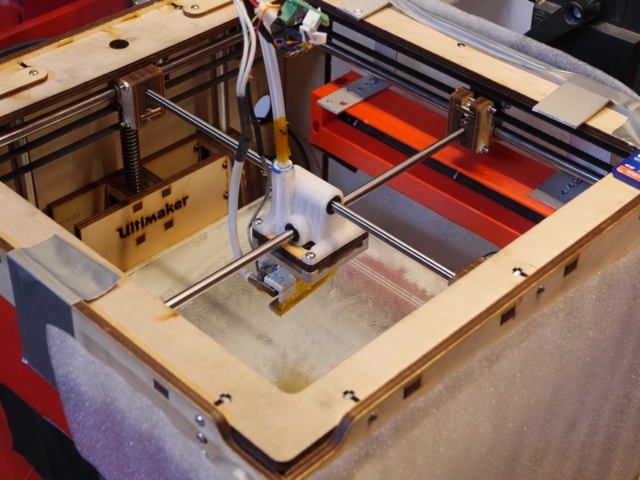
I stopped using a printhead-attached device for cooling. Instead I went for a cross flow fan like http://www.conrad.de/ce/de/product/560546/X-Fan-Querstromluefter-Motor-rechts-DF43198-R-12-V-400-mA and mounted it to one side of the housing.
What you get is:
- a (- well almost -) laminar air flow covering the whole print area at nozzle height +/- 1-2 cm.
- lots of air volume (138 m3/h)
- silence ... compared to many other fans
- no issues with luff and lee so far (can even be improved with an adapted print head design which directs some air downwards)
- an opportunity for a kind of air curtain for realizing a heated chamber without covering the top
- ...
Of course you need a thermal insulation for the hot end like MadOverlord's.
It's working very well so far and might be a building block for a modified printer design I started thinking about.
Holy crap, that's an awesome idea!
I will be updating my mold in a few days so that it doesn't cover the top of the hot block. The current design was reducing the temperature gradient too much, resulting in increase clogs. You can simply cut that area of the silicone away from the current version of course.
Time to share some experience: You might consider throwing away your printhead fans ...
I'm using this setup for some weeks now and never experienced corners lifting of or parts warping. Seems to work for bigger parts and smaller parts like the robot or bridging as it addresses both, the warping and the cooling problem, fairly well.
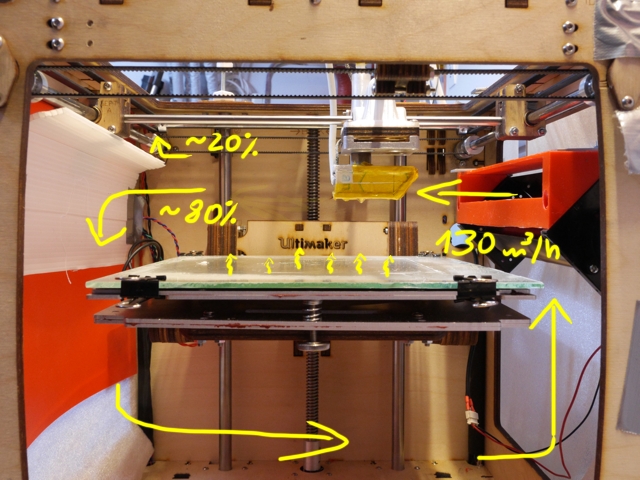
The current setup is basically a kind of topless convection oven.
Just Nick's minimum printhead with nothing attached, except a thermal insulation for the heater block. All 3 three open sidewalls covered and a heated bed with the wood glue mix.
A crossflow fan with huge 130 m3/h air volume blows at z height 0 +/- 10 mm and acts like an air curtain as well. I bought an anemometer, so the 20% and 80% are quite accurate.
The fan is always on. For printing PLA, bed is set to 40-50°C. Air temperature within the printer is typically two or three degrees lower. So even without a covered top, most of the heat energy stays within the printer.
The "cooling" air is some degrees warmer compared to a normal setup but it seems, that the huge air flow covering the whole printing area outweighs this by far. Which might also be true for the luff and lee issue.
Looks very interesting. Checking out crossflow fans has been on my todo list for a while, but I've been busy with a KickStarter. My mold for a standard hot-end thermal sock may come in handy...
Awesome! This solution is just what i needed. I am currently tinkering on my own printhead design and had problems figuring out where to put those fans and ducts to provide sufficient airflow without making the head bigger.
This could solve my problems.
Indeed, as Ultimaker went for the 1st price in the "maximum print envelope with minimum footprint" competition there is almost no space for fans or ducts which provide more air flow. One motivation why I started thinking in that direction.
This is so good. How are you powering the fan? I see that most crossflow fans are 12V, but can the main PCB handle the current?
How is the noise?

ArunC posted a topic in UltiMaker 3D printers,


.thumb.jpeg.0b7a05eafc09add17b8338efde5852e9.jpeg)

ArunC posted a topic in UltiMaker Cura,


Recommended Posts
Top Posters In This Topic
30
25
14
8
Popular Days
Sep 8
9
Sep 7
8
Sep 20
8
Sep 16
6
Top Posters In This Topic
madoverlord 30 posts
foehnsturm 25 posts
owen 14 posts
nick-foley 8 posts
Popular Days
Sep 8 2013
9 posts
Sep 7 2013
8 posts
Sep 20 2013
8 posts
Sep 16 2013
6 posts
tz-advantage 0
I have a compressor with a 60l tank at 100-120 psi, i am going to try using that for cooling.
Have to find a good regulator to lower the pressure, don't want to blow away the pieces.
Link to post
Share on other sites