

yes, should have been cleared, it is the rail system.

yes, should have been cleared, it is the rail system.
I noticed a lot of extrusion issues when printing especially with "tougher" materials or when reaching 60 percent of the spool. helping the feeder by hand helped, but that's not something i want to do during a 24 hour print.
[...]
i tried moving the material.to better fit the feeder. i ended up with UltiArjans solution last week and the be honest, this solved everything with the STOCK feeder.
It looks like some UM2 feeders take a tighter grip of the filament than the others. In my case, the feeder was biting the filament way too hard - even when adjusted to be as gentle as possible.
However, I agree with you - the UM2 stock feeder is not _that_ bad. The overall filament path just has many problems... It works better for full spools than for half empty ones. The grinded side of the filament gets to the "outer track" in the Bowden tube. There's too much friction in spool rotation - and if you add bearings, the filament may jump off the spool.
Most of my problems were solved by changing the filament path - although I also needed another feeder:

one sidenote, i have noticed the motors becoming incredible hot. not just the feeder, but all of them. i have attached some Fluke temperature sensors to them now and will post some results. i don't know the factory specs but they seem to get into the 60 degrees celsius range..
Stepper motors are not very sensitive for high temperatures. Mine are running around 80C, no problems  I'm using 1.5A current for the feeder stepper motor - and the others are inside my closed chamber where I normally have my print bed at 110C.
I haven't read every post in this topic, so maybe this has been covered before.
Does anyone have any good tips for disassembling and reassembling the feeder?
I just replaced the feeder with Robert's design, and it's working great, but I find the motor falling down annoying.
Here's what I did, is there a better way?
1. put the ultimaker 2 face down (feeder up), remove spool holder for working room.
2. unscrew feeder. motor will fall down about 10 cm
3. Partially assemble new feeder, and place over hole (move the motor around first so at least one of the holes line up.)
4. Use extra 30 mm screws (I ordered 10) to pull the motor up in two holes.
5. insert the "stock screws in the other two holes and tighten. You may have to lift the extruder gear to reach, but the holes should line up.
6. remove the long screws, and replace with the stock ones.
I thought about trying to remove the sheet metal thingy, but was afraid some nut would fall down and then I'd have a bigger disassembly job on my hands.Does anyone know? Is there a disassembly guide I've missed? (googling and searching this forum hasn't helped.)
Thanks, (and thanks iRoberti for your great feeder!)
Kevin
I left it standing normally. Worked facing the back of the printer and had plenty of space. I removed the screws, hold the motor knot and put it to rest within the hole because of the knot sticking out so it was fairly easy to put it back in place with the new feeder.
I just do it like this:

I'm lazy
Yes, those are in fact pliers
I remove the white cover, unscrew all but one screw, grab the stepper with one hand and unscrew the last screw with the other, place the stepper on the platform, put one screw into the new feeder (top right usually) and put it on the printer, place the screwdriver onto the screw, grab the stepper with the other hand and place it so that I can get the first screw going, check that no wires are caught (guess why...), tighten up the screw finger tight (so I can wiggle the motor a bit), and from there it's just a matter of putting in the other screws and tightening everything up.
I don't know if that's the best way but it's how I've done it the last 20-30 times.
I thought about trying to remove the sheet metal thingy, but was afraid some nut would fall down and then I'd have a bigger disassembly job on my hands.Does anyone know?
I have taken the white sheet metal thingy out and I'm not planning to put it back. In my opinion it's too close to the print head rear fan and the nozzle block wiring when the head is parked. Also, it causes the 2 stepper motors to heat up even more than they do without the metal wrap. The good thing about it is - it's easy to remove
Could someone use a knurling tool head? something like mcmaster part 3330A32?
you could potentially use 2 of these (one on each side of the filament) spring loaded together and then linked with a single gear attached to the drive motor. That way you can set up the gear ratio to match the original diameter of the knurled piece on the stepper?
I have something in mind but I have to sketch it out.
Holoy moly. I installed Roberts feeder and I increased my possible printing volume for 4mm^3/s to 24mm^3/s without skippings occuring.
I was expecting a slight improvement, but not that much!
Is there any feed rate setting in Cura that can be used to compensate for a different diameter on the extruder wheel? I think just a larger extruder wheel would make a big difference. Especially if it is a straight groove instead of the knurl.
One thought on belt drives. The belt really only grips the filament where the wheels sit. So you could get the same effect using rubber wheels as you get by using a belt.
That was my feeling too, more or less. I.e. that two wheels are better than a belt, because there would be no belt to stretch, slip or wear out.
However I wouldn't go with rubber wheels. I do understand the intuition that led to that suggestion, but IMHO rubber would itself wear and slip. My choice would be two knurled wheels, ideally tuned so that they both run in each other's indentations - we don't want the filament to be chewed up more than it needs to be, e.g. during retraction-heavy prints.
My understanding of the weakness of the existing design is that if you go for a powerful motor (UM1), it grinds the filament and stalls the print. If you go for a weaker motor (UM2), it can still grind the filament, but if it doesn't do that then it jumps back, causing underextrusion.
It seems to me that if you had two points of contact on the filament then you could go back to a stronger motor, but have a reduced risk of grinding. I.e. each wheel would act as a backup for the other, and the load on the filament would be distributed.
yeah. driving both wheels would likely help a lot. or just larger diameter wheels to get a larger contact patch.
@DonMilne A knurled wheel + two rubber wheels may work better than the belts. I've been debating if I want to modify my extruder design to use two rubber wheels instead as the rubber belts causes a number of issues if the belts have too much slack. The idea behind the belts was that the more contact area = more friction against the filament but there are more variables to consider if the belts are not 100% tightened. One thing to note is that the filament will slip even if the filament does not jump back (ie. stepper motor does not skip) so just using two knurled wheels by itself may not solve the problem if there are a large number of consecutive retractions. I'll likely try to modify my design to use http://www.mcmaster.com/#2473k11 and a http://www.mcmaster.com/#4747a61 rather than belts in the near future.
Hi everybody!
Some input that might be interesting for those working on improving the feeder mechanism:
Lately I have been experimenting a lot with geared stepper motors. The increased torque on the feeder axis helps a lot in achieving higher extrusion rates. However, printing with a very high number of retractions is still problematic: during these prints the filament gets flattened and obstructs the bowden tube. I have been measuring the temperature of the feeder wheel axis; during long prints (with a room temperature of 22 degC) the feeder wheel axis reaches temperatures between 40 and 43 degC. At this temperature PLA already gets quite a bit softer than at room temperature. During continuous extrusion this is not problematic, however during prints with lots of extrusions it is.
Cheers!
Bas

The ideal feeder mechanism for PLA will be the one which applies uniform pressure around the filament (360°).
Re the mention of geared steppers: bear in mind that increasing the motor torque, while necessary, isn't enough by itself. All that happens is that we reach the stress failure limit of the filament itself, i.e. we get grinding. If we want to return to a stronger motor then we need to distribute the force.
I assume the 360° suggestion means 3 or 4 drive wheels around the filament? That might be ideal in the sense of distributing the load, but wouldn't it complicate filament loading? Also, we'd be losing the spring loaded idler bearing, so maybe it wouldn't cope as well with varying filament diameters.
Yes, the closest realization might be a four wheel solution where one wheel nearly touches 80° of the filament (concave wheel surface). It would be a bulky setup but with a clever spring mechanism it should be possible to even allow for different filament diameters.
Hi everybody!
Some input that might be interesting for those working on improving the feeder mechanism:
Lately I have been experimenting a lot with geared stepper motors. The increased torque on the feeder axis helps a lot in achieving higher extrusion rates. However, printing with a very high number of retractions is still problematic: during these prints the filament gets flattened and obstructs the bowden tube. I have been measuring the temperature of the feeder wheel axis; during long prints (with a room temperature of 22 degC) the feeder wheel axis reaches temperatures between 40 and 43 degC. At this temperature PLA already gets quite a bit softer than at room temperature. During continuous extrusion this is not problematic, however during prints with lots of extrusions it is.
Cheers!
Bas
And that is why i cool my feeder motor..... called it (mainly because otherwise the Feeder holder made out of Pla could get deformed, but who would think that the heat would stop there?)
You should still be able to spring load something like this, the gears would retract to load filament and if you size it right then you can get this thing to grab the filament pretty darn hard.

Yes, the closest realization might be a four wheel solution where one wheel nearly touches 80° of the filament (concave wheel surface). It would be a bulky setup but with a clever spring mechanism it should be possible to even allow for different filament diameters.
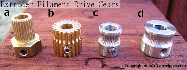
A four wheel solution is overkill and would make any maintance probably very hard. Also nearly as good would be a 2 Wheel solution where both wheels would form a Circle. On the side of the grove of each wheel they would need to be flat ( otherwhise you would have problems with different diameters that affect the filament), sort of like the Mk7 Drive Gear but with a smaller diameter like in this picture (D) and even a lager flat part on each side of the grove.
I still think just going to a pair of driven wheels of a larger diameter will make a huge difference.
A quick sketch shows it has a lower angle for the filament to enter so loading would be easier. There is also 20% more contact area on each side. To keep the stepper rotating at the same rate there would have to be a matching gear reduction prior to hitting the drive sprockets.

You would lose a lot of torque on larger wheels.

MariMakes posted a topic in UltiMaker Cura,


ArunC posted a topic in UltiMaker 3D printers,


Recommended Posts
Top Posters In This Topic
120
118
52
37
Popular Days
Feb 10
33
Feb 25
29
Feb 13
26
Mar 27
23
Top Posters In This Topic
ian 120 posts
IRobertI 118 posts
Blizz 52 posts
geeks 37 posts
Popular Days
Feb 10 2014
33 posts
Feb 25 2014
29 posts
Feb 13 2014
26 posts
Mar 27 2014
23 posts
Posted Images
geeks 1
Hello there,
Well here it is, six months my room without turning evil. This morning surprise, the mobile arm that pushes the filament against the knurled part dropped. Delaminated to be exact!
I've put in a new version. To see if you want to try. This makes the rigid part and the setting of the spring is less sensitive than before. The question is that it will give in time
Some pictures of the new room:
The files are available in the same location as the extruder V2: https://www.youmagine.com/designs/extruder-um2-version-2#!design-documents
Link to post
Share on other sites