


Torgeir
-
Posts
1,234 -
Joined
-
Last visited
-
Days Won
26
Content Type
Forums
Events
3D Prints
Everything posted by Torgeir
-
UM2+ feeder upgrade for UM2?
Torgeir replied to gregwar's topic in Third party products & modifications
Hi Lies, Absolutely you'll need to upgrade the firmware to make the motor change direction - as well. Thanks Torgeir. -
Hi Silures, When you are using your multi meter as shown, you are measuring between one power wire for the heat bed and one sensor wire from the PT100 temp sensor. The voltage you see here is normal, but have no meaning for our use.. Actually there should be no voltage present to the heat bed as your PT100 temp sensor is not working correctly! When measuring the heat bed power, you have to measure between the two gray wires. When measuring the PT100 sensor you measure between the two black wires. Your printer should never been powered when doing this measuring as we do not measure voltage, but resistance. So, disconnect the bed temp sensor when measuring resistance (as gr5 adviced), (no power on the printer) and measure on your bed between the two terminal points where the two black wires are connected. If you find the resistance to be between (108-112) ohm your PT100 is probably OK. Next point to measure is at the connector (still unconnected to the main PCB). As you already have swapped temp 1 and temp 3, we know that your bed temp sensor is out of tolerance. Carry out the above test, using the setting on your multi meter as shown on the added picture. Then measure at the connector using needle or wire links from arduino kits etc. Here is the first picture of your multi meter indicating the correct setting for measuring resistance. Here is a picture of how to measure a PT100 temp sensor at the connector. Zoom in to see the two other places might be used.. Note: When measuring resistance, connect red and black pin together and check that the resistance is 0 ohm or very close to zero! When those to pin is disconnected from each other the reading is normally OL (open line). Good luck. Thanks. Torgeir.


-
Hi Lance, I'm very sorry to hear this. As I've read trough your description of the failure, this must be a kind of slow heating (restricted current) that is detected over "some time" by the firmware that stop the program due to a heater failure. Could this be the power wires for the heat bed, connection at the bed terminal or at the main PCB. If there is such a failure there is always some sign of overheating where the failure occur. Color change, brownish burnt etc. Also look at the feeder cables, if there is an interrupted connection along the cable some place you will see this easily. Since this occur at a certain level of height, the failure might be in the bed power feeder. Look at the strain relief at the bed as the wire tend to break here or, at the other place where the wire also may bend in the inner left corner. The error code / observation is just the same in both cases. Hope you find the problem and good luck. Thanks. Torgeir
-
Hi again.. Too bad that internet is not very good right here. Lost 90 percent of the mail.. So see you sometime next week. Torgeir.
-
Hi Silures, As I've had to go to Ireland, there was no way to answer in here.. Well, you see the power of this site, lots of help in here.
-
Hi Silures, This is kind of strange as you said you measure 20 V at the heat bed.. Cause the whole printing program normally stop and there should not be any voltage present at the terminal point were the two grey wires are connected. Well, unless there is some other firmware allowing this (?) -but doubt in this matter. If you use the resistance function of your multi meter, does it show close to 0 ohm when the measuring pins are shorted? Further, across the two terminal screws (use the pins directly on the two screw for the temp sensor), here the resistance should be around (108-110*) ohm in room temperature? (*)Edited The problem with the PT100 sensor have often been located to the terminal contact point. Those two black wires are kind of tiny, so strip the insulation twice as long as needed then twist each of the wires a litte and fold it back so the length of bare wire is correct. The idea of this is to obtain more of area into the clamping and make the conduction better at this point. Same can actually be done for the two power wires, yes in this case -only on the board with screw terminals. Thanks. Torgeir.
-
Hi birdy100, It does not matter as the whole heath bed is floating. I.E. None of the two connector terminals for the heath bed are connected to ground. Same is true for the PT100 temp sensor on the heath bed, where the two black wires are connected. Thanks. Torgeir.
-
Hi Silures, Well, what happened when you swapped the connectors Temp1 and Temp3? If the failure swapped from Temp3 to Temp1, you have a faulty wiring for bed temperature! So, If this is true, it should be very simple to confirm by using an ohm meter. Note; if there is an intermittent failure in this wiring, the failure may come on an go off as the bed is riced or lowered. This due to an intermittent contact when the wiring is moving due to bed height level changes. If nothing changed, you have some failure in the firmware (telling there is a bed temp error) or that there is a real hardware failure on your main PCB. The statement of this check will tell us what part of the system we'll find the error / the failure. So what happened? Thanks. Torgeir.
-
Heated Bed Errors - Screw Terminal? pt100?
Torgeir replied to nerdwarrior's topic in UltiMaker 3D printers
Hi nerdwarrior, You should change this Terminal Block. Here is a picture I made from the terminal block to see the connector lip in half way closed position. The material in here is Tin plated Copper. Maybe we can see this lip if you turn the screw clockwise to lift the lip. Did the wires for the heat bed show any sign of overheated, burnt black etc.? If you touch (trying to heat) the PT100 resistor with your finger, there should not be any big jump in the reading - maybe 1 ohm "more", this cause the aluminium plate is connected to the resistor. Here is the P/N number of the used Terminal Block: MKDS 1/ 4-3,81 SMD And here is where you find them: http://www.tme.eu/gb/details/mkds1_4-3.81smd/pcb-terminal-blocks/phoenix-contact/mkds-1-4-381-smd-bk-1727256/ OK., good luck. Thanks Torgeir.
-
Hi Silures, Welcome in here. This error indicate that there is an error with the PT100 as the resistance is out of tolerance. And this is the only errors that immediately end the printing program.. The right thing to do here is to measure the PT100 resistance from the connector located at the main PCB "TEMP3". Remove this connector and measure the resistance on this connector (should be around 108 ohm at room temperature (22 deg C)). You could also swap the two connectors TEMP1 and TEMP3 to see the failure will swap from "heat bed sensor" to "temp sensor". This wiring from the hear bed to the PCB should last very long, but in some cases they break or suffer for intermittent contact at the heat bed connector. Go to this place to find more info about the system, also download the UM2 manual to find more information if needed. https://ultimaker.com/en/resources/160-error-messages Thanks. Torgeir.
-
Hi Lance, Here is some pictures of the process. This is the first error I've got. Here is the faulty relay K1. Faulty relay removed from PCB, solder to be removed from mounting holes. New relay installed beside the heating outputs, 3 ea. The stepper motor output drivers, 5 ea -and all seven receive power from K1! This picture is made just before the PCB cover is installed. (Note, there is no brownish color around the stepper drivers due to heat, could this be due to the two fan installed?) This last picture show the two brands of relay I found, including the Arduino 2 relay module holding same types of relay as installed on the PCB I have in my printer. OK., this was all and good luck. Thanks. Torgeir.


-
Hi xenon, Have a close inspection to the "led wiring" going around the corners to the upper horizontal led strip. Make sure there is no contact toward the pulleys or shafts. Another weak point might be where the led wiring is routed through the hole in the fwd left corner (toward the bottom located PCB). Good luck. Thanks, Torgeir.
-
Hi Lance, Two weeks ago I've changed the "24" VDC master relay on the main board (UM2). This relay can make lots of troubles and give all the warnings related to the "power" users of 24 VDC and those are: All of the stepper motors, and all three heater's (three if you have a Mark 2). There is actually no warning telling you that the 24 VDC (from the master relay) is missing, this could be a good thing to add into next generation hardware/firmware.. The thing is that if this relay starting to arching (voltage is dropping over a certain time), any of those warnings can shows up due to a missing or interupting 24 VDC and such warning is actually false and misleading.. As I had this problem, got all kind of "strange" warning until I realized all of them had a common power source and all of them was powered via the 24 VDC relay. The funny thing is this; one day when feeding the filament using the advanced menu I could have an error saying: X or Y end stop error and then the firmware halted with an error number I cant remember, but.. Later on, this one; ERROR - STOPPED Heater error Go to: ultimaker.com/ERØ3 The printer may be switched off, then on again and may work for some time, but you will sooner or later have a total failure of this relay that have to be changed. As I had to go to KL (Kuala Lumpur) for a week, I used this opportunity to search for this kind of relay. I found two brand of this relay type: 1) SRD-05VDC-SL-C Blue colored plastic housing (Brand name Songle) 2) HK3FF-DC5V-SHG Black colored plastic housing (Brand name HUI KE) The coil voltage is 5 VDC and contacts current is 10 A at 30VDC However, I've also found that this same relay (the one with the blue colored plastic housing) is used in the Arduino relay modules, so this migt be handy to know for someone.. So to a little warning; this relay is not that easy to remove without damaging the PCB track. Here you will need some special skills and tools – now you're warned! I made some pictures of the repair, if of interest I'll add them here. Well, just my 5p. Good luck. Thanks Torgeir.
-
Hi bmeehan19, What you assume here sounds quite right, -however, this approach should normally not destroy your PCB... So was this really what happen??? OK., anyway you should measure the input voltage to the FET, the voltage from PG5 into the resistor R54. This voltage should be at lo stage, less than 0.4 volt (approx). If this is true your FET Q1 needs to be replaced. You could also short the R57 right across the resistor -and NOT to any convenient ground point around -but across the resistor itself. If the light goes out, your processor is to be blamed -or changed... When you indicate this is the problem, you sure have an electronics background... So go on and do this test and please report back. Thanks. Torgeir.
-
Hi Folks, I've also seen this problem in the very beginning, but I made a shim of "post it labels" (cut exactly to fit) and this is what I'm using in my printer. It never come loose anymore. You may select a type of paper with less thickness, this to avoid to hi tension, as this can make the black sliding unit to crack -like it's seen on some of the first generation UM3. Thanks. Torgeir.
-
Hi foehnstrum, I'll been following this tread for a "loong" time and must say; this is the most valuable "gift" to the Community I've ever seen in here (IMO). The print we see here is as perfect as it could be in the important places, the blades of the propeller. Very impressive! "I'm talking about the Mark 2 print!" Thanks for sharing all this with us. Torgeir.
-
object is sliced differend from what I designed
Torgeir replied to herman-wouters's topic in UltiMaker Cura
Hi Herman, Just had a look at your model, at first I thought it was good, but when I went close in to the model I found some problem.. Well, -to be able to have a model perfectly sliced by Cura the model have to be a whole solid body. Your model have some parts around that's not properly connected together, so Cura will see different object and cannot slice it properly. Your model have to be "joined" as one part. Good luck. Thanks. Torgeir. -
Hi mtm4ck, I have two HP laptop, one Pavilion G4 with an AMD Radeon HD 7670M and the other one an old HP/Compaq 6910p. Both of them is running Cura 2.5 (the best version so far of this new generation of Cura IMO), as with all the other versions there have been some issues. The "one" I've had problem with is the old Cura setup files, "somehow" those are not always compatible with next new version of Cura. If you have had old versions of Cura installed, you'll need to delete the (sometime hidden) Cura setup files, or just rename the directory/catalog for those files. Another strange thing with HP (my experience), is that; if you go into the "setup" in your computer, you'll see a HP name instead of the real"AMD Radeon" display"processor". So upgrade of those drivers has to be done at HP's web site. Well, you probably did that?? Just my 5 p. Thanks Torgeir.
-
Hi womacki, My pleasure! Great job you've done there. Thanks for reporting back. Torgeir.
-
A better Bed Glass - Neoceram Glass
Torgeir replied to neotko's topic in Third party products & modifications
Hi neotko, This was really interesting -and you're a true experimenter!!! The Schott company is a real high end supplier of all kind of special glass. Great info! Thanks. And a happy weekend. Torgeir. -
Hi Max, This looks like you have to much play in the linear bearing(s) in the extruder unit. To inspect this, (the printer do not have to be switched on) hold the extruder from above with your left hand to prevent it move, then use your right hand from below grab the lo part of the extruder without touching the wiring on the reverse side of it. Now try to move the extruder at this place forward/aft for the Y axis to see if there is any play. Do the same thing right/left (the X axis). If there is to much play here, you will see clear opening in first layers.. This is a test to be repeated in different positions for the extruder, as such play can be related to spesific positions.. OK. Good Luck. Thanks Torgeir. Edit: The four sliding bearing on the 4 X 8 mm shafts may also cause such error, but same procedure will cover those as well. For those bearing (inside each of the four black sliding blocks), you can also feel play when moving those block (carefully) up and down, much forces must not be used here.
-
Hi TAGood827, Welcome in here. You already got good info from SyntaxTerror, but here's some more good news. I found this crimping tool (very good quality) from China, where most of this stuff come from these days.. Have a look here: https://www.aliexpress.com/snapshot/7332700156.html?orderId=72901719139774&productId=32506636704 I bought this one, as I built my "UM2" (customised) and can advice this dealer and the tool for the connector used on the printer. I've been working for many years with such tools and say; 16.50 USD for this one is less than 10 % of the price offered from our dealers in Europe or US. Good luck. Thanks. Torgeir.
-
VERY challenging "Gaps Between Infill and Outline" solving
Torgeir replied to bastienb's topic in UltiMaker 3D printers
Hi bastienb, Sorry to hear that, but sure if you're depending of the printer that's the best way to go. Good luck and please report back the findings. Thanks. Torgeir. -
VERY challenging "Gaps Between Infill and Outline" solving
Torgeir replied to bastienb's topic in UltiMaker 3D printers
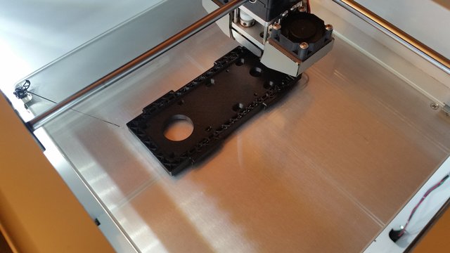
Hi bastienb, Yesterday I could not find an examples of how my first layer look like, but here it is: First view is from the inner side of the printer, observe the reverse side of the extruder head. This is first layer with brim and the color of the filament is black! Also you can see how the transparency changes due to bed offset. This next picture is the same print seen from the front side into the printer and still first layer. The bed addition is excellent, no need for glue here. Then a picture of the second layer. And finally a picture of the object being printed, (a new belt gearbox for my printer). Well, this is the way I'm doing it and now I'd never seen any object come loose from the bed, however, for parts with small footage -glue is a must.. Thanks. Torgeir.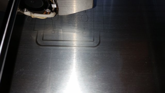


-
VERY challenging "Gaps Between Infill and Outline" solving
Torgeir replied to bastienb's topic in UltiMaker 3D printers
Hi bastienb, Great, you still have much to much filament flow.. Even if I wish it was the knurled wheel, I have to say it's not bad at all.. What I now think is that when you had trouble feeding the 1.75 nozzles, the feed rate is brought sky high somehow, maybe the feed needed to be increased in order to get enough flow to avoid under extrusion that time? Then the problem with to lo retraction, nozzle leak/sip etc. A factory reset will bring back the original default setting, then check your filament type, size, temp and nozzle size. That's all, I'll think.. Cross my fingers.. Thanks. Torgeir. Oh.. forgot one thing. When adjusted this close, my method, make sure that the initial layer height is 0.15 mm (not 0.3 as Cura 2.5.0 use as default.)


